
Automated instrumentation and method for measurements of samples

Active Publication Date: 2010-08-12
WALLAC
View PDF15 Cites 28 Cited by
  • Summary
  • Abstract
  • Description
  • Claims
  • Application Information

AI Technical Summary

Benefits of technology

[0024]The present teachings provide an automated instrumentation for assaying and measuring samples wherein described disadvantages of the prior art are avoided or reduced. The object is therefore to achieve effective instru

Problems solved by technology

However, it is generally not possible to have different kinds of assays with possibly different chemistries simultaneously processed in those instruments.
It is not possible to move any other sample plates during the processing of one sample plate situated on the conveyor.
And during the transfer, it is not possible to utilise the processing units which are located by the conveyor.
This increases the required overall processing times. Therefore the known automated instruments are practically limited to performing one type of assay successively at any time.
Therefore, it is difficult if not impossible to perform assays of different types possibly including different chemistries simultaneously in an automated instrument.
The known automated instruments do not provide all functions required for different kinds of assays.
However, the automated systems generally have constant washing procedures which may not be suitable or at least optimized for all types of measurements.
It is also difficult to update new functions to the known instruments because the instruments have no required space or required interfaces for additional functional units.
However, since the known autom

Method used


Image

  • Automated instrumentation and method for measurements of samples
  • Automated instrumentation and method for measurements of samples
  • Automated instrumentation and method for measurements of samples

Examples


Example

DETAILED DESCRIPTION OF DRAWINGS

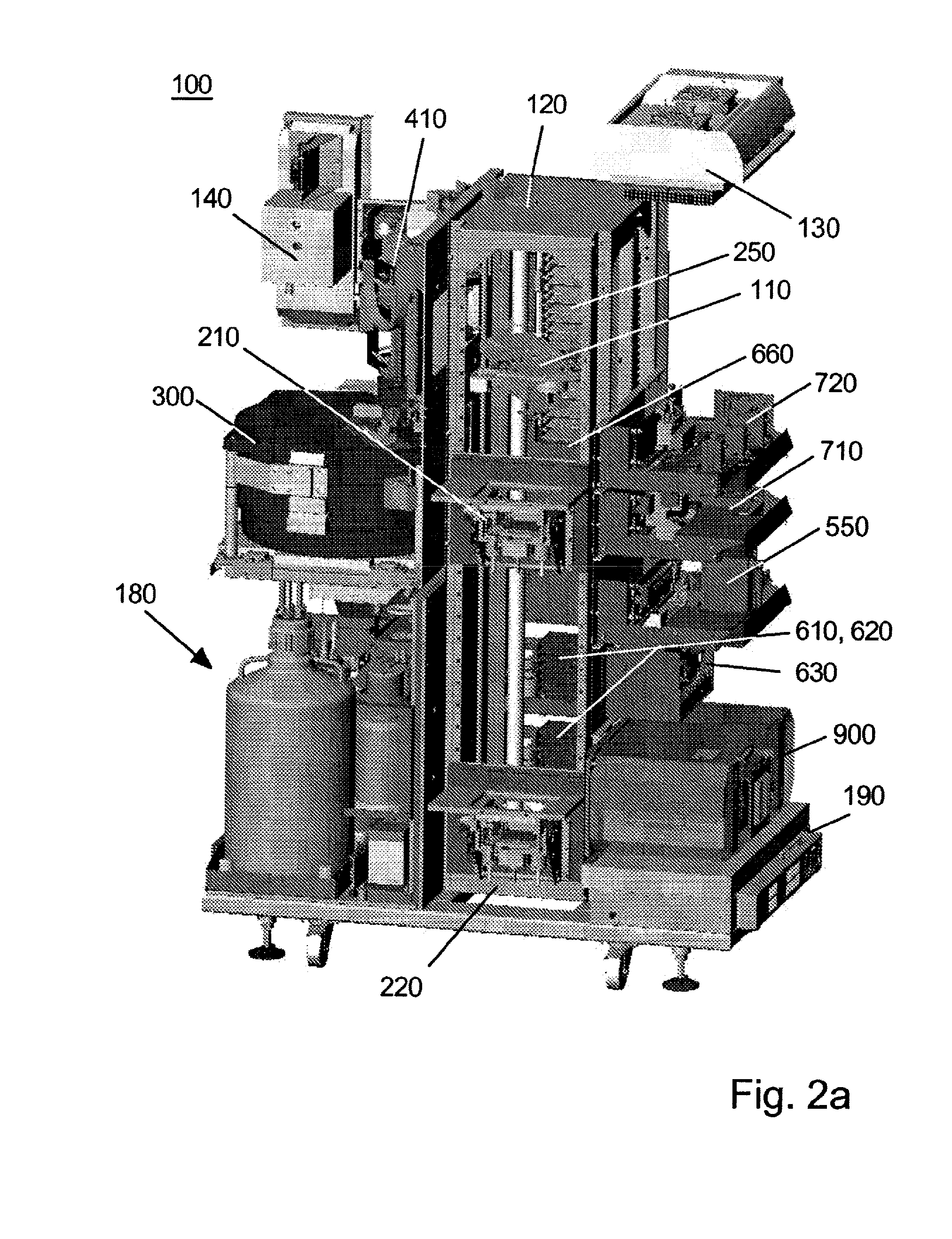
[0187]FIG. 2a illustrates an exemplary automated instrument. The instrument includes following functional units:[0188]an input stacker unit 210 for loading sample plates;[0189]an output stacker unit 220 for unloading sample plates;[0190]a plate storage unit 250 for temporary storing and possibly incubation of sample plates;[0191]a reagent storage unit 300;[0192]two dispensing units 410 for dispensing reagents from the reagent storage unit to sample wells;[0193]a bulk reagent dispenser 550 for dispensing reagents from bulk reagent containers to sample wells;[0194]a first shaking incubator unit 610, a second shaking incubator 620 unit and a third shaking incubator unit 630 for shaking and / or incubation in fixed temperature;[0195]an incubator 660 with adjustable temperature and sealed enclosure;[0196]a disc remover 710 for removing blood spot discs from sample wells;[0197]a washing unit 720 for removing liquids from sample wells;[0198]a measurement unit ...


PUM


Abstract

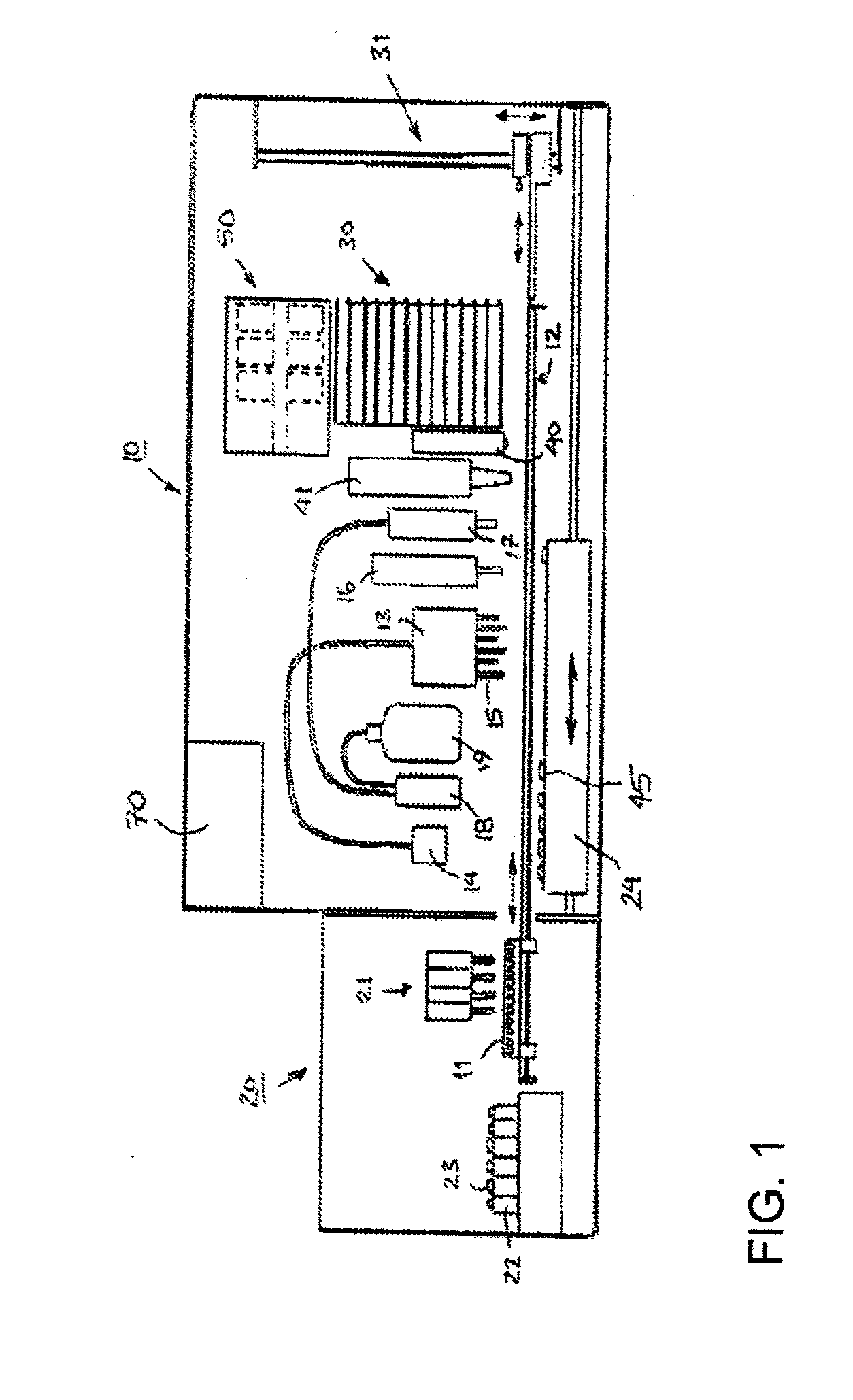
One object of the invention is to provide instrumentation and a method for efficient and reliable assaying and measuring samples. The teachings include an automated self-contained instrument for assaying and measuring samples, wherein the samples are located on wells of sample plates, and the instrument comprises a plurality of units for processing or storing sample plates. The instrument according to the teaching may comprise at least one dispensing unit for dispensing reagents or other assay components to the sample wells, at least two units for simultaneously processing or storing a plurality of sample plates, at least one unit for removing substance from the sample wells, and one or several measurement units, the measurement unit(s) providing a capability for the instrument to optically measure samples in at least two measurement modes. Further, the instrument comprises a manipulator having a capability to move the sample plates in three orthogonal directions or combinations thereof and to rotate the sample plates in relation to a vertical axis for transferring the sample plates to the units.

Description

TECHNICAL FIELD[0001]The present teachings relate generally to the field of biochemical laboratory instrumentation for measuring compounds in samples using microtitration plates or corresponding sample supports.BACKGROUND[0002]The routine diagnostics and research in analytical, clinical and biochemical laboratories is often based on biochemical assay methods using different tags or labels coupled to specific reagents allowing sensitive and specific determination of desired compounds in the samples. The typical labels e.g. in immunoassays are different radioactive isotopes, enzymes, different luminescent and fluorescent molecules, for example those of chelates of rare earth metals.[0003]The detection of the analyte can be done directly based on the label, or indirectly, as is done for example in enzymatic assays and in immunoassays. Enzyme immunoassays (ELISA) are often based on enzyme substrate molecules labelled with a reporter group, which upon enzymatic reaction is turned into li...

Claims


Application Information

Patent Timeline
IPC IPC(8): C12Q1/02C12M1/34C12M1/36
CPCG01N2001/288G01N35/028Y10T436/11G01N35/1002G01N2035/00108G01N35/0099G01N2035/00326
Inventor HEINONEN, AARNEKARUNEN, JUHAKORPI, JARMONURMI, JARMOOJALA, MARKKUSALMINEN, TIMOSALONEN, JANNETORSTI, ILARIVARJONEN, MARKKUWHITE, PAUL
Owner WALLAC
Learn More