Magnetic Head Suspension

a technology of magnetic head suspension and supporting parts, which is applied in the direction of head support, record information storage, instruments, etc., can solve the problems of increasing the inability to keep the distal end section flat upon the formation of the boss portion, and the inability to keep the distal end section flat, so as to reduce the thickness and reduce the weight of the supporting part , the effect of preventing the lowering of a resonant frequency

Active Publication Date: 2010-08-12
SANCALL CORP
View PDF17 Cites 6 Cited by
  • Summary
  • Abstract
  • Description
  • Claims
  • Application Information

AI Technical Summary

Benefits of technology

The present invention provides a magnetic head suspension that includes a supporting part with a boss portion fixed by swage to a carriage arm connected to an actuator, a load bending part that is supported by the supporting part and generates a load for pressing a magnetic head slider towards a disk surface, a load beam part that transmits the load to the magnetic head slider, and a flexure part that supports the magnetic head slider. The invention achieves reduction in thickness and weight of the boss portion, prevents deterioration of the flatness of the first supporting member, and improves production efficiency without reducing the resonant frequency. The invention also provides a rib region that connects the first and second supporting members, which achieves stable connection without requiring strict dimensional accuracy. The rib region may include a single rib, multiple ribs, or a combination of both.

Problems solved by technology

Accordingly, in a case where the supporting part integrally includes the boss portion and a distal end section for supporting the load bending part, it is difficult to keep the distal end section flat upon formation of the boss portion.
The flatness of the distal end section of the supporting part cannot be kept particularly in a case where the distal end section is provided with a hole or a groove in a complex shape.
However, such a general supporting part has problems that an area of the supporting part at which the boss portion is positioned has an increased thickness in a through-thickness direction (in a z direction) perpendicular to the disk as well as that the weight of the supporting part is increased.
As a result, there arise the following problems.
In a case where the outer diameter of the base plate is smaller than the inner diameter of the hole due to variation in size, the base plate can be easily fitted in the hole, but insufficient joint strength between the base plate and the proximal portion lowers the resonant frequency of the magnetic head suspension.
To the contrary, in a case where the outer diameter of the base plate is close to the inner diameter of the hole due to variation in size, it is difficult or impossible for the base plate to be fitted in the hole.
If the base plate is forcibly pressed into the hole, a load is applied to the proximal portion and thus the flatness of the proximal portion is deteriorated.

Method used


Image

  • Magnetic Head Suspension
  • Magnetic Head Suspension
  • Magnetic Head Suspension

Examples


first embodiment

[0044]Hereinafter, one preferred embodiment of a magnetic head suspension according to the present invention will be described, with reference to the attached drawings.

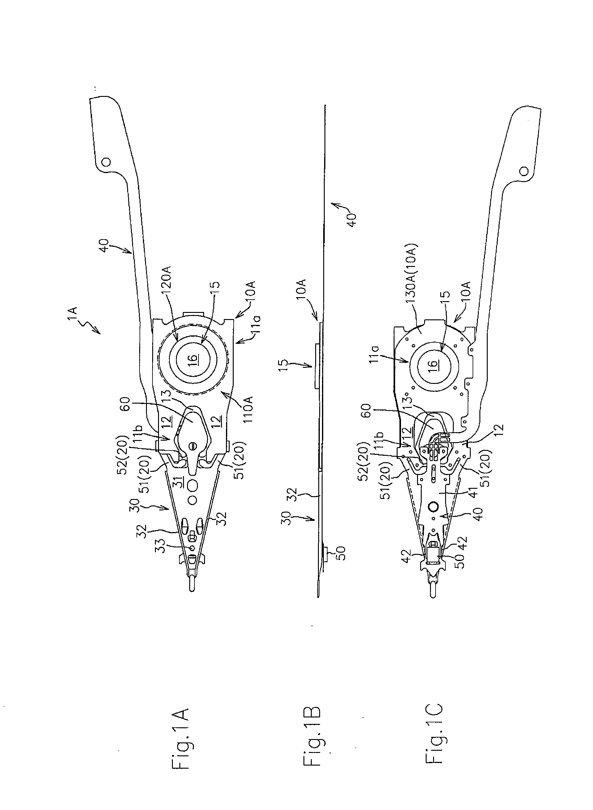
[0045]FIGS. 1A to 1C are a top view (a plan view as viewed from a side opposite from a disk surface), a side view and a bottom view (a bottom plan view as viewed from a side close to the disk surface) of a magnetic head suspension 1A according to the present embodiment, respectively. FIG. 1C indicates welding points with using small circles.

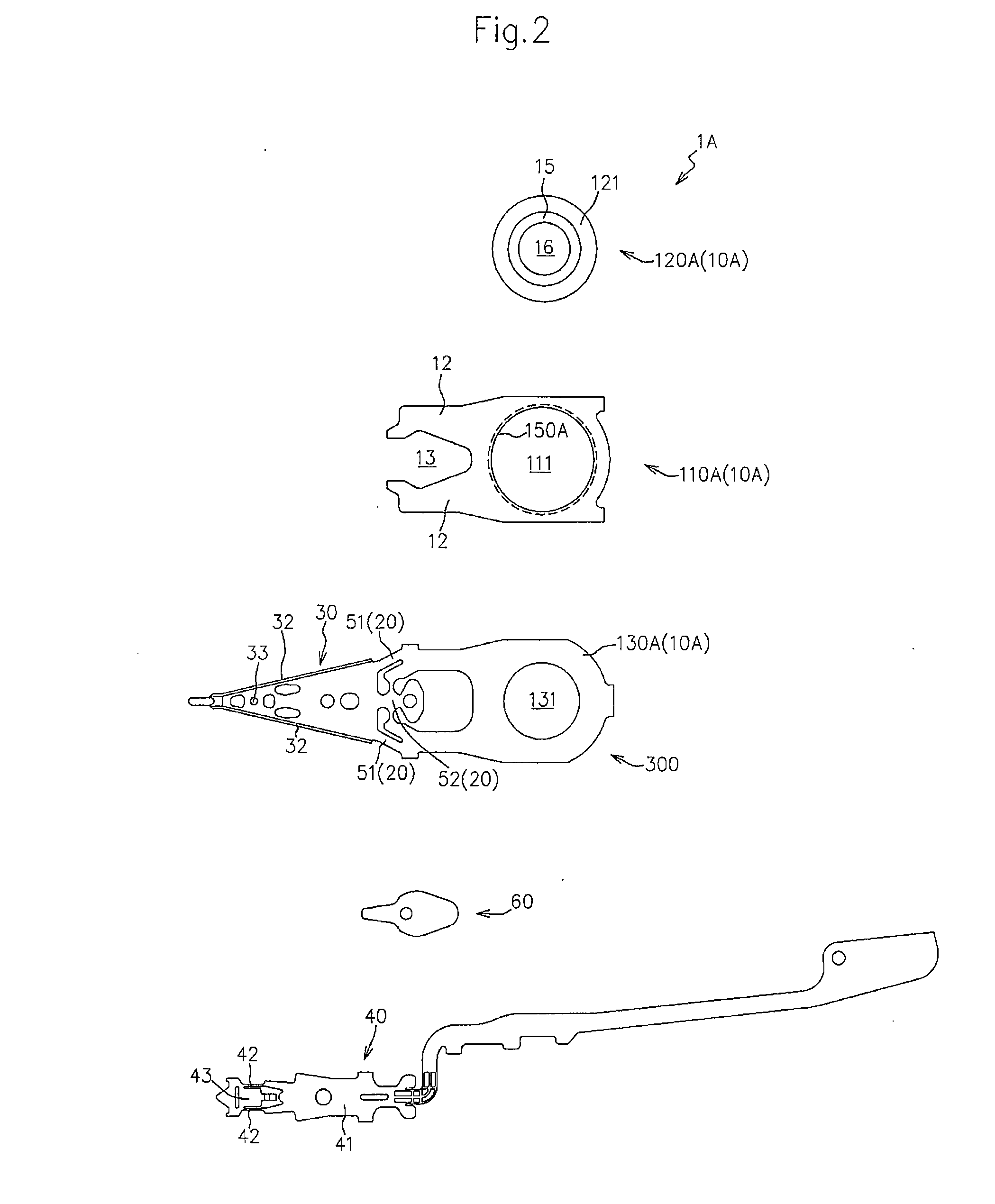
[0046]FIG. 2 is an exploded plan view of the magnetic head suspension 1A.

[0047]As shown in FIG. 1A to FIG. 1C and FIG. 2, the magnetic head suspension 1A includes a supporting part 10A that includes a boss portion 15 fixed by swage to a carriage arm (not shown), which is connected to an actuator (not shown), a load bending part 20 that is supported by the supporting part 10A and generates a load for pressing a magnetic head slider 50 toward a disk surface, a load beam part 30 that ...

second embodiment

[0140]Hereinafter, another embodiment of the magnetic head suspension according to the present invention will be described, with reference to the attached drawings.

[0141]FIG. 9A is a top view of a second supporting member 120B in a magnetic head suspension according to the present embodiment, and FIG. 9B is a cross sectional view taken along line IX(b)-IX(b) in FIG. 9A.

[0142]FIG. 9C is a top view of a first supporting member 110B in the magnetic head suspension according to the present embodiment, and FIG. 9D is a cross sectional view taken along line IX(d)-IX(d) in FIG. 9C.

[0143]FIG. 9E is a vertical cross sectional view of the first and second supporting members 110B and 120B in a state of being connected with each other.

[0144]In the figures, the members same as those in the first embodiment are denoted by the same reference numerals to omit the detailed description thereof.

[0145]The magnetic head suspension according to the present embodiment is different from the magnetic head s...

third embodiment

[0150]Hereinafter, still another embodiment of the magnetic head suspension according to the present invention will be described, with reference to the attached drawings.

[0151]FIG. 10A is a top view of a second supporting member 120C in a magnetic head suspension according to the present embodiment, and FIGS. 10B and 10C are cross sectional views taken along lines X(b)-X(b) and X(c)-X(c) in FIG. 10A, respectively.

[0152]FIG. 11A is a top view of a first supporting member 110C in a magnetic head suspension according to the present embodiment, and FIGS. 11B and 11C are cross sectional views taken along lines XI(b)-XI(b) and XI(c)-XI(c) in FIG. 11A, respectively.

[0153]FIG. 12A is a top view of the first and second supporting members 110C and 120C in a state of being connected with each other, and FIGS. 12B and 12C are cross sectional views taken along lines XII(b)-XII(b) and XII(c)-XII(c) in FIG. 12A, respectively.

[0154]In the figures, the members same as those in the first and second e...


PUM

PropertyMeasurementUnit
thicknessaaaaaaaaaa
thicknessaaaaaaaaaa
thickaaaaaaaaaa

Abstract

It is an object to achieve prevention of lowering resonant frequency and improved production efficiency while achieving reduction in weight of a supporting part with a boss portion and reduction in thickness at area at which the boss portion is located. In the present invention, the supporting part includes a first supporting member with which a load bending part is connected, and a second supporting member with the boss portion and a main body region extended radially outward from the boss portion. At least one of the inner periphery of the mount hole and the outer periphery of the main body region is integrally provided with a rib region. The first and second supporting members are connected to each other by a restoring force of the rib region that has been elastically and / or plastically deformed by the other one of the inner periphery of the mount hole and the outer periphery of the main body region with the main body region being located at least partially in the mount hole in a through-thickness direction.

Description

BACKGROUND OF THE INVENTION[0001]1. Field of the Invention[0002]The present invention relates to a magnetic head suspension for supporting a magnetic head slider that reads and / or writes data from and to a recording medium such as a hard disk drive.[0003]2. Related Art[0004]A magnetic head suspension for supporting a magnetic head slider includes a supporting part that is connected to an actuator by way of a carriage arm, a load bending part that is supported by the supporting part and generates a load for pressing the magnetic head slider toward a disk surface, a load beam part that is supported by the supporting part via the load bending part and transmits the load to the magnetic head slider, and a flexure portion that is supported by the load beam part and supports the magnetic head slider.[0005]More specifically, the supporting part has a boss portion, and is supported indirectly by the actuator with the boss portion being fixed to the carriage arm by swage.[0006]The boss porti...

Claims


Application Information

Patent Timeline
Patent Type & Authority Applications(United States)
IPC IPC(8): G11B21/16
CPCG11B5/4833
Inventor FUJIMOTO, YASUOMASHIMO, KENJI
Owner SANCALL CORP
Why Eureka
Try Eureka