
Ice/beverage dispenser with in-line ice crusher

a technology for beverage dispensers and dispensers, which is applied in the direction of liquid handling, lighting and heating equipment, instruments, etc., can solve the problems of difficult dispensing of previously-crushed ice, ice makers, beverage dispensers that do not allow room for crushers, and beverage dispensers that do not allow crushers. to be used, so as to increase the height or the footprint of the dispenser

Inactive Publication Date: 2010-08-12
MANITOWOC FOODSERVICE CO LLC
View PDF15 Cites 9 Cited by
  • Summary
  • Abstract
  • Description
  • Claims
  • Application Information

AI Technical Summary

Benefits of technology

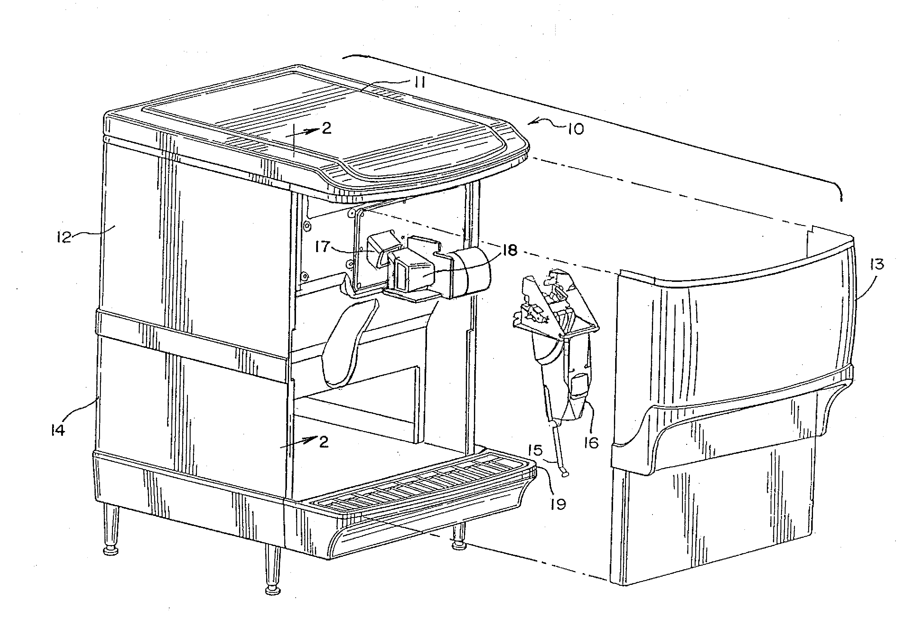
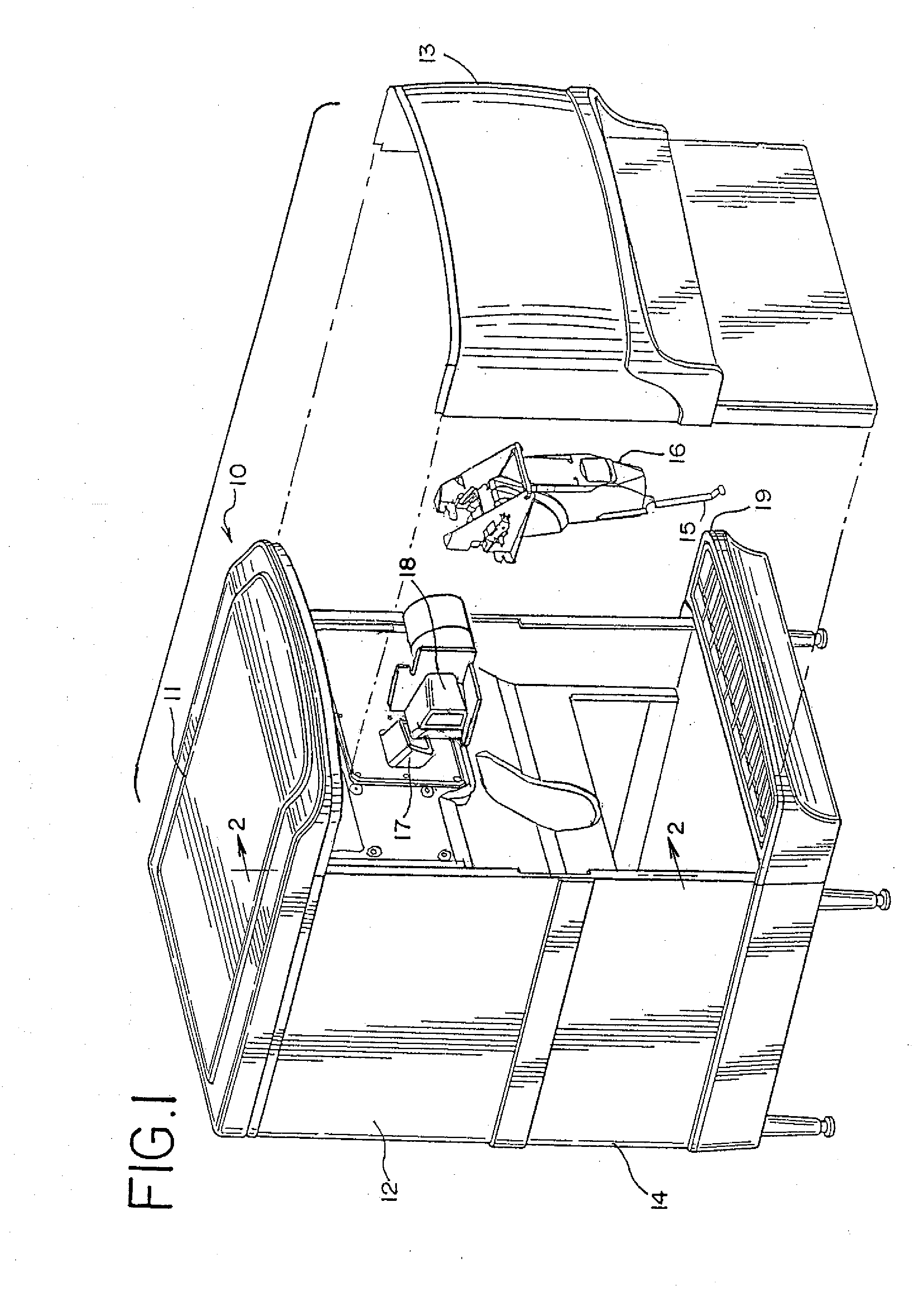
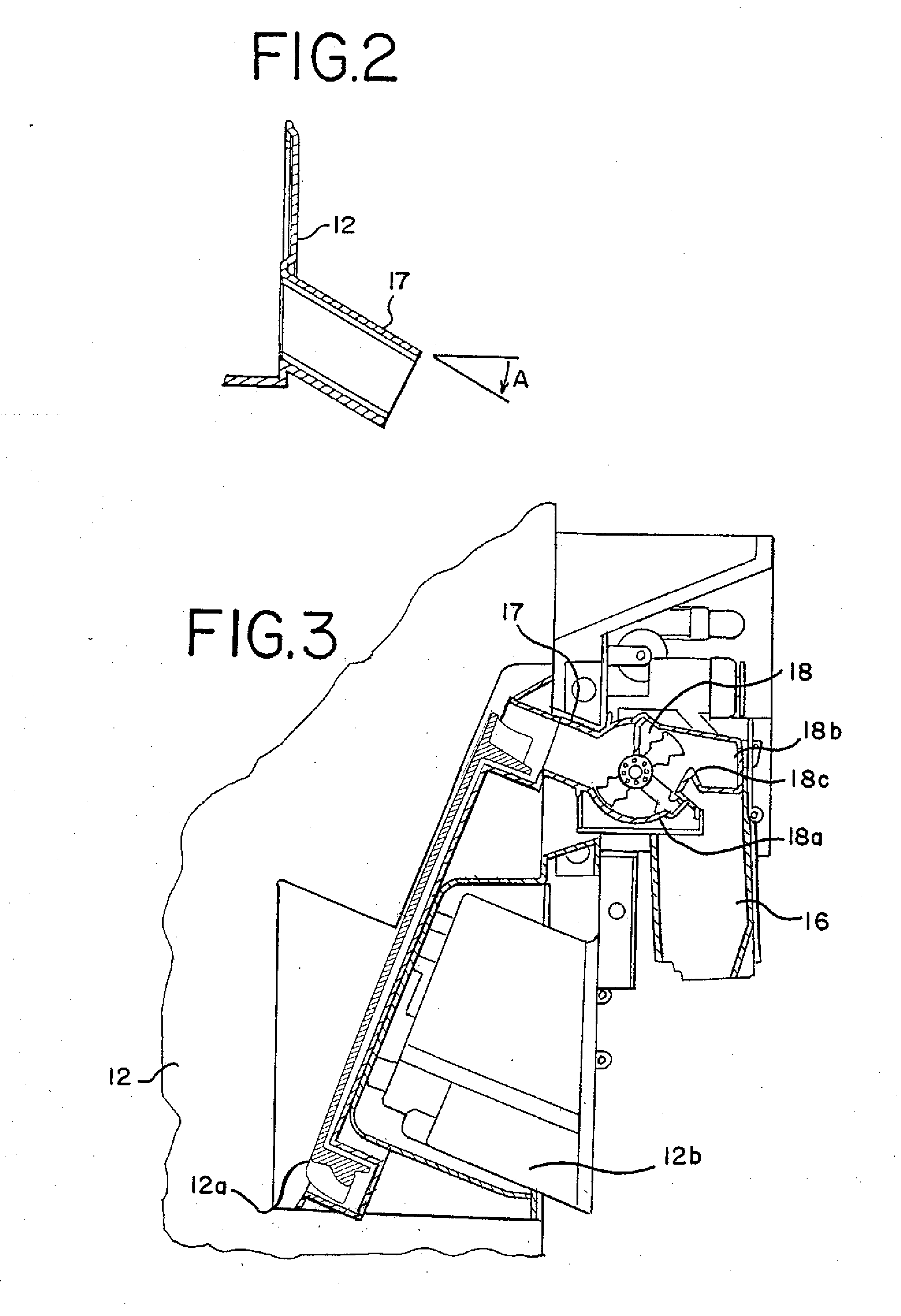
[0006]An ice dispenser with an integrated ice crusher has been invented which now makes it possible to provide crushed ice at the point of ice delivery to a customer's cup. The small size and arrangement of the ice crusher allows the ice crusher to be integrated into the dispenser without significantly increasing either the height or footprint of the dispenser. The integrated ice crusher can also be used on a combined ice and beverage dispenser. Preferred ice and beverage dispensers allow for the delivery of either crushed or cubed ice according to the consumer's choice.

Problems solved by technology

One problem with dispensing ice is that ice makers, ice bins and ice dispensers require space in very crowded serving and dining areas.
The same problem of lack of space acts as a barrier to the addition of an ice maker or an ice crusher.
Dispensing previously-crushed ice is difficult, as in U.S. Pat. No. 6,109,476, since the ice tends to form clumps in the ice bin and may not readily be conveyed from the bin.
In addition, the design of beverage dispensers typically does not allow room for a crusher to be easily placed into an existing dispenser.
Low ceilings or other obstacles to height may make this additional height objectionable.

Method used


Image

  • Ice/beverage dispenser with in-line ice crusher
  • Ice/beverage dispenser with in-line ice crusher
  • Ice/beverage dispenser with in-line ice crusher

Examples


Embodiment Construction

[0047]The terms “cubed ice” and “ice cubes” as used herein and in the claims refers to ice frozen in a piece, regardless of its shape. Ice cubes can be rectangular in shape, round, or of some other shape.

[0048]There are many embodiments of this invention. Preferred embodiments include an ice dispenser with an ice crusher that dispenses and crushes ice (FIG. 1), and combined ice and beverage dispensers with an ice crusher. In this later category there are three types of equipment: those that dispense both crushed and cubed ice through the same ice dispensing chute (FIG. 4 shows one embodiment of this type and FIGS. 18-22 show another embodiment of this type), those that dispense crushed and cubed ice though different dispensing chutes (FIG. 6 shows one embodiment of this type and FIGS. 23-26 show another embodiment of this type), and those that dispense only crushed ice (not shown in any particular figures).

[0049]While other types of ice crushing mechanisms may be used, in general th...


PUM


Abstract

An ice crusher is attached to an ice dispenser or to a combined ice and beverage dispenser. The ice crusher occupies minimal space in order to fit the dispenser into an existing space on a serving counter or in a beverage dispensing area. The ice crusher may also elevate the ice. In embodiments using this technique, the outlet of the ice from the ice crusher is higher than the ice inlet. As the ice flows from a source of ice, such as an ice bin, the ice is elevated while it is being crushed. The ice then flows from the outlet of the ice crusher down an ice chute or other outlet of the ice crusher, into a cup or container as desired. Other embodiments convey the ice without lifting it, and still other embodiments dispense either crushed or cubed ice, as the consumer may select. In one embodiment the selected crushed ice or cubed ice are both dispensed though the same ice dispensing chute. A retrofit kit may be used to add an ice crusher to an existing ice dispenser, or to an existing combined ice and beverage dispenser.

Description

REFERENCE TO EARLIER FILED APPLICATIONS[0001]The present application is a divisional application of U.S. patent application Ser. No. 11 / 514,715, filed Sep. 1, 2006, which claims the benefit under 35 U.S.C.§119(e) of Provisional U.S. Patent Application Ser. No. 60 / 713,983, filed Sep. 2, 2005; both of which are hereby incorporated by reference in their entirety.TECHNICAL FIELD[0002]The technical field of the invention is that of ice dispensers, and ice and beverage dispensers.BACKGROUND[0003]Commercial ice dispensers, such as those used in fast-service restaurants, are built in a compact design to increase the ice storage area within a given space. Many customers of fast-service restaurants, as well as consumers generally, are accustomed to having ice in their beverage. Of course, this means that there must be an ice dispenser nearby, or the beverage dispenser may include an ice bin and an ice dispenser. In some applications, such as one depicted in U.S. Pat. No. 6,761,036, assigned t...

Claims


Application Information

Patent Timeline
Patent Type & Authority Applications(United States)
IPC IPC(8): B67D7/00B67D7/80
CPCF25C5/046Y10S62/17F25C2400/08F25C5/04B67D3/00F25C5/00
Inventor LANDERS, JERRY L.THOMPSON, GREGORY K.SLONE, WILLIAM DEREKGLASS, GREG A.GRADY, JOHN M.
Owner MANITOWOC FOODSERVICE CO LLC
Learn More