
Variable volume containment for energy storage devices

a technology of energy storage devices and volume containment, which is applied in the direction of sustainable manufacturing/processing, flat cell grouping, batteries, etc., can solve the problems of device damage, device may not work properly, and the net volumetric shift of the container

Inactive Publication Date: 2010-07-29
G4 SYNERGETICS INC
View PDF16 Cites 40 Cited by
  • Summary
  • Abstract
  • Description
  • Claims
  • Application Information

AI Technical Summary

Benefits of technology

"The patent describes apparatus and methods for ESDs (electrostatic discharge) that have variable volume containment. One embodiment includes an ESD with a stack of bi-polar electrode units, each containing a conductive substrate, a positive active material electrode layer, and a negative active material electrode layer. An electrolyte layer is provided between each pair of adjacent electrode units, and a flexible gasket is positioned about each electrolyte layer. Another embodiment includes an ESD with cell segments that have a first and second conductive substrate with an active material electrode layer each, and an electrolyte layer between them. Hard stops are provided to set the inter-electrode spacing of the ESD. These technical effects provide improved performance and reliability of ESDs in various applications."

Problems solved by technology

Each of these materials undergoes state changes which result in a net volumetric shift within the container.
The pressures attributed to the changing active material states also cause electrode surfaces to physically press against container walls.
If the stress exceeds the capability of the containment device, the device may be compromised and may not function properly.
These structures require strict accounting of the materials within the rigid container because the container does not allow volumetric expansion and / or contraction (i.e., the amount of free volume is fixed).
The amount of free volume may affect the operation of the ESD as too much free volume results in poor performance (e.g., a loose cell) and too little free volume results in a potentially explosive device.
In some instances the forces generated during operation of these conventional ESDs may exceed the material limits of the container and cause the container to rupture.
When the container ruptures due to high pressures, the internal constituents are ejected with a significant amount of energy.

Method used


Image

  • Variable volume containment for energy storage devices
  • Variable volume containment for energy storage devices
  • Variable volume containment for energy storage devices

Examples


Embodiment Construction

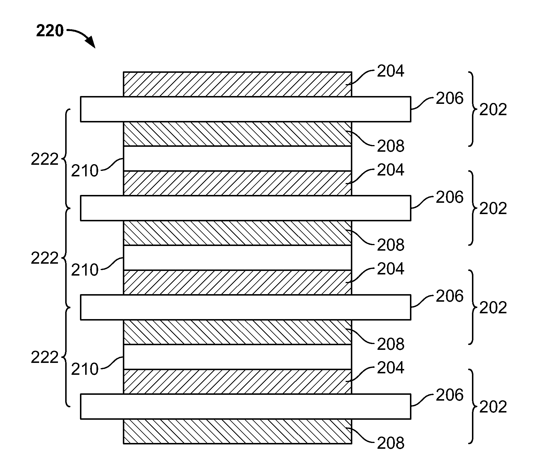
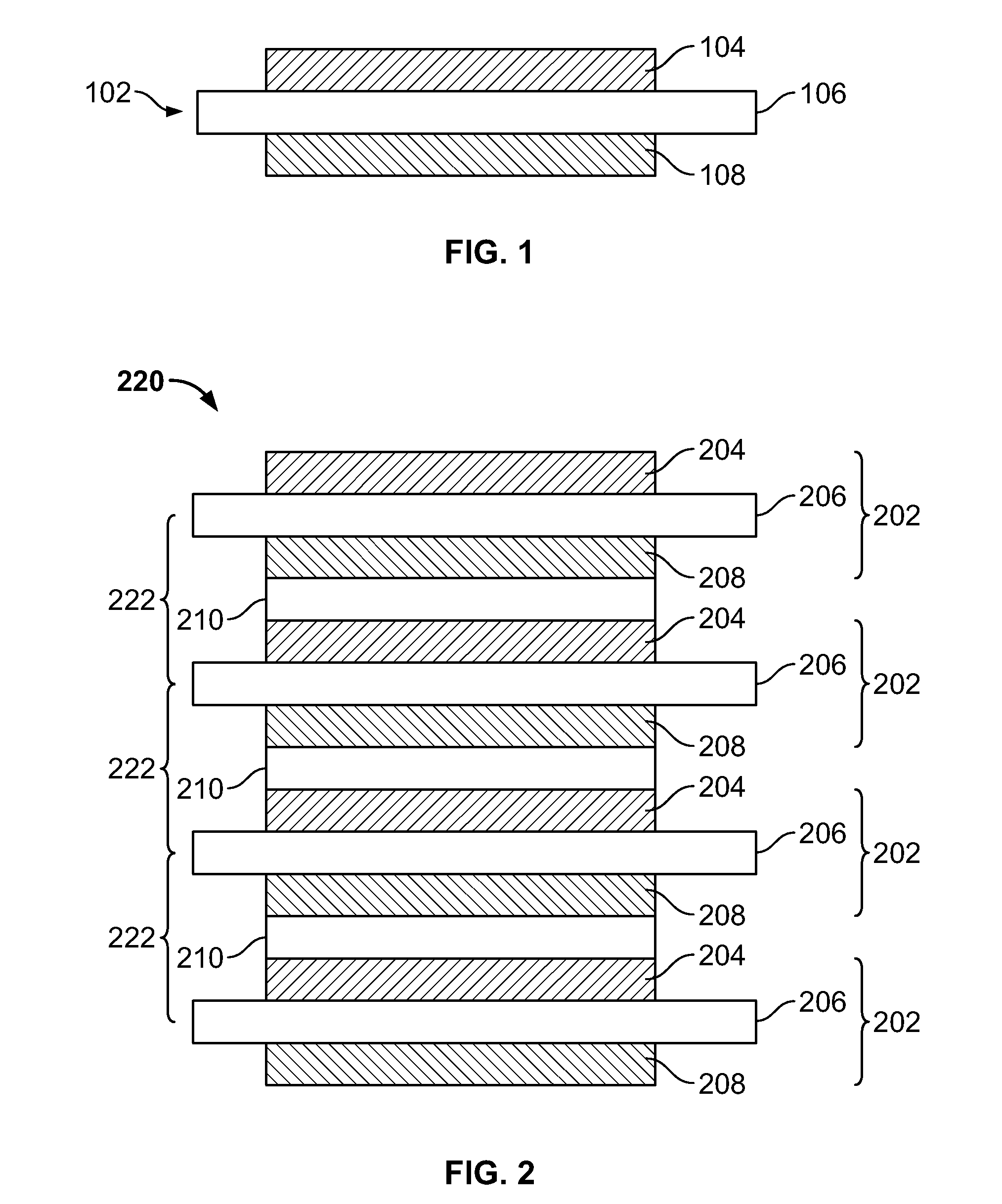
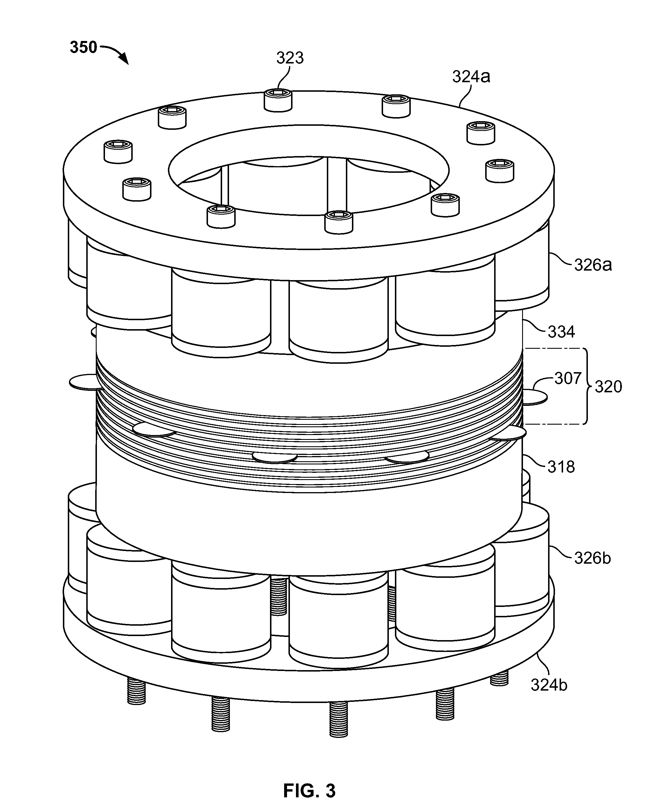
[0026]Apparatus and methods are provided for energy storage devices (ESDs) having variable volume containment, and are described below with reference to FIGS. 1-15. The present invention relates to ESDs such as, for example, batteries, capacitors, or any other suitable electrochemical energy or power storage devices which may store and / or provide electrical energy or current. It will be understood that while the present invention is described herein in the context of a stacked bi-polar ESD having variable volume containment, the concepts discussed are applicable to any intercellular electrode configuration including, but not limited to, parallel plate, prismatic, folded, wound and / or bi-polar configurations, any other suitable configuration, or any combinations thereof.

[0027]As defined herein, “inter-electrode spacing” is the distance between active material electrode layers in a stacked bi-polar ESD. This may be applied, for example, to the distance between a positive and negative ...


PUM

PropertyMeasurementUnit
gap distancesaaaaaaaaaa

Abstract

A stacked energy storage device (ESD) has at least two cell segments arranged in a stack. Each cell segment may have a first electrode unit having a first active material electrode, a second electrode unit having a second active material electrode, and an electrolyte layer between the active material electrodes. Variable volume containment may be used to control the inter-electrode spacing within each cell segment. In some embodiments, one or more dynamic flexible gaskets may be included in each cell segment to seal the electrolyte within the cell segment and to deform in preferred directions. In some embodiments, hard stops may set the inter-electrode spacing of the ESD.

Description

CROSS-REFERENCE TO RELATED APPLICATION[0001]This application claims the benefit of U.S. Provisional Application No. 61 / 147,725, filed Jan. 27, 2009, and U.S. Provisional Application No. 61 / 181,194, filed May 26, 2009, both of which are hereby incorporated by reference herein in their entireties.FIELD OF THE INVENTION[0002]This invention relates generally to energy storage devices (ESDs) and, more particularly, this invention relates to ESDs that incorporate variable volume containment.BACKGROUND OF THE INVENTION[0003]A feature of sealed ESDs is containment and isolation of the cells within the ESD from external contamination and / or interference. Conventional containment devices (e.g., ESD wrappers) provide containment and isolation for the various phases of the ESD materials, such as the electrolyte solvent mixture and the active materials. It is often necessary to contain these ESD materials while the cells are in rest or in operation. While the cells are in rest or in operation ce...

Claims


Application Information

Patent Timeline
Patent Type & Authority Applications(United States)
IPC IPC(8): H01M6/48H01G9/26H01M6/42H01M50/184H01M50/186H01M50/198H01M50/463H01M50/474H01M50/477
CPCH01M2/08H01M10/4214H01M4/70H01M6/48H01M10/0413H01M10/0418H01M10/044H01M10/045H01M10/0477H01M10/28H01M10/282H01M10/286H01M10/4235Y02E60/124H01M2/06H01M10/0468H01M2004/029H01M2/18H01M50/198H01M50/463H01M50/186H01M50/477H01M50/474H01M50/184Y02E60/50Y02E60/10Y02P70/50H01M50/172H01M8/02H01M8/04H01M50/183H01M50/40H01M2220/20
Inventor WEST, JON KENNETHHIGGINS, MARTIN PATRICKHIGGINS, EILEENREGALADO, JULIUSGEORGE, ANTHONYZHOU, XINCITTA, NELSONCITTA, MYLESMICHAEL, ALLENCHERISOL, KENNETHWEST, DANIEL J.PATTERSON, BARBARA
Owner G4 SYNERGETICS INC
Learn More