
Radio transmission device, radio reception device, and precoding method

a radio reception device and transmission device technology, applied in the field of radio transmission devices, radio receiving devices and precoding methods, can solve the problems of inter-symbol interference, deteriorating error rate performance, spectrum of a signal that propagates through such a channel, etc., and achieve the effect of improving error rate performan

Inactive Publication Date: 2010-07-29
PANASONIC CORP
View PDF4 Cites 5 Cited by
  • Summary
  • Abstract
  • Description
  • Claims
  • Application Information

AI Technical Summary

Benefits of technology

[0010]The present invention makes it possible to improve error rate performance, in mobile communication where precoding is combined with FDE.

Problems solved by technology

If such wideband transmission is performed in mobile communication, it is known that a communication channel becomes a frequency selective channel formed with a plurality of paths of varying delay times. Therefore, with wideband transmission in mobile communication, preceding symbols interfere with subsequent symbols, causing inter-symbol interference (“ISI”) and deteriorating error rate performance.
Further, in a frequency selective channel, the channel transfer function fluctuates in the frequency band and therefore the spectrum of a signal that propagates through such a channel is received and is distorted.

Method used


Image

  • Radio transmission device, radio reception device, and precoding method
  • Radio transmission device, radio reception device, and precoding method
  • Radio transmission device, radio reception device, and precoding method

Examples


embodiment 1

[0024]With the present embodiment, in case where THP is combined with FDE, transmission data is modulated according to the second modulation scheme of the first modulation scheme and second modulation scheme.

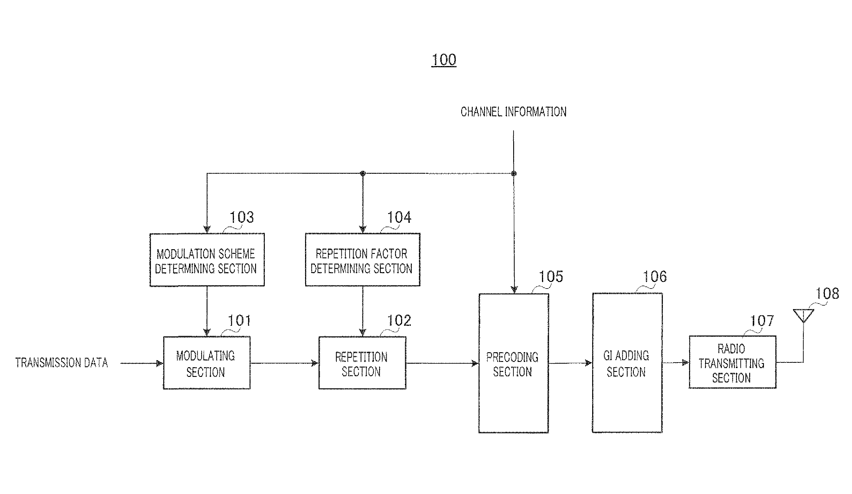
[0025]With the present embodiment, a radio transmitting apparatus transmits single carrier signals subjected to THP, to a radio receiving apparatus, and the radio receiving apparatus performs FDE of the single carrier signals. Further, there are radio receiving apparatuses according to the present embodiment that perform FDE, and, in addition, radio receiving apparatuses that do not perform FDE. Hereinafter, the configurations of the radio transmitting apparatus and radio receiving apparatus according to the present embodiment will be explained. FIG. 3 shows the configuration of radio transmitting apparatus 100 according to the present embodiment, and FIG. 6 shows the configuration of radio receiving apparatus 200 according to the present embodiment that performs FDE.

[0026]In ra...

embodiment 2

[0059]With the present embodiment, transmission data is modulated by one of the first modulation scheme and the second modulation scheme, and THP is applied to symbol sequences generated using the second modulation scheme and is not applied to symbol sequences generated using the first modulation scheme.

[0060]FIG. 9 is a block diagram showing the configuration of radio transmitting apparatus 300 according to the present embodiment. Note that the same components as in the configuration of radio transmitting apparatus 100 (FIG. 3) of Embodiment 1 will be assigned the same reference numerals and explanation thereof will be omitted.

[0061]In radio transmitting apparatus 300 shown in FIG. 9, modulating section 301 modulates transmission data according to the modulation scheme notified from modulation scheme determining section 302, to generate a symbol sequence formed with a plurality of symbols. By this means, a block in which a symbol sequence is arranged in the time domain is formed. T...


PUM


Abstract

Provided is a radio transmission device which can improve an error ratio characteristic in a radio communication system which performs precoding. There are two types of modulation methods: a first modulation method having a small error ratio improvement width by precoding and a second modulation method having a large error ratio improvement width by precoding. In the radio transmission device (100), a modulation unit (101) modulates transmission data by the second modulation method so as to generate a symbol, a copying unit (102) copies the symbol so as to generate a plurality of symbols, and a precoding unit (105) performs precoding of the symbols.

Description

TECHNICAL FIELD[0001]The present invention relates to a radio transmitting apparatus, radio receiving apparatus and precoding method.BACKGROUND ART[0002]To realize data rates over 100 Mbps for the next generation mobile communication system, various studies are underway for radio transmission schemes that are suitable for high speed packet transmission. Because it is necessary to widen the bandwidth of the frequency band to be used to perform such high speed packet transmission, studies are going on to use the bandwidth around 100 MHz.[0003]If such wideband transmission is performed in mobile communication, it is known that a communication channel becomes a frequency selective channel formed with a plurality of paths of varying delay times. Therefore, with wideband transmission in mobile communication, preceding symbols interfere with subsequent symbols, causing inter-symbol interference (“ISI”) and deteriorating error rate performance. Further, in a frequency selective channel, the...

Claims


Application Information

Patent Timeline
Patent Type & Authority Applications(United States)
IPC IPC(8): H04L27/00H04L27/20
CPCH04L1/0005H04L1/0011H04L1/0038H04L2025/0342H04L25/03159H04L25/03343H04L1/08Y02D30/50
Inventor MIYOSHI, KENICHITAKAOKA, SHINSUKEADACHI, FUMIYUKITOMEEA, HIROMICHITAKEDA, KAZUKI
Owner PANASONIC CORP
Learn More