
Methods and devices for coding and decoding an image sequence represented with the aid of motion tubes, corresponding computer program products and signal

a motion tube and image sequence technology, applied in the field of coding and decoding of image sequences, can solve the problems of irregular meshes, poor representation of real motion, and cost overhead in terms of compression bitrate,

Active Publication Date: 2010-07-29
FRANCE TELECOM SA
View PDF9 Cites 24 Cited by
  • Summary
  • Abstract
  • Description
  • Claims
  • Application Information

AI Technical Summary

Benefits of technology

[0018]transition information cues, making it possible to update said reference block at least one instant t of said sequence;
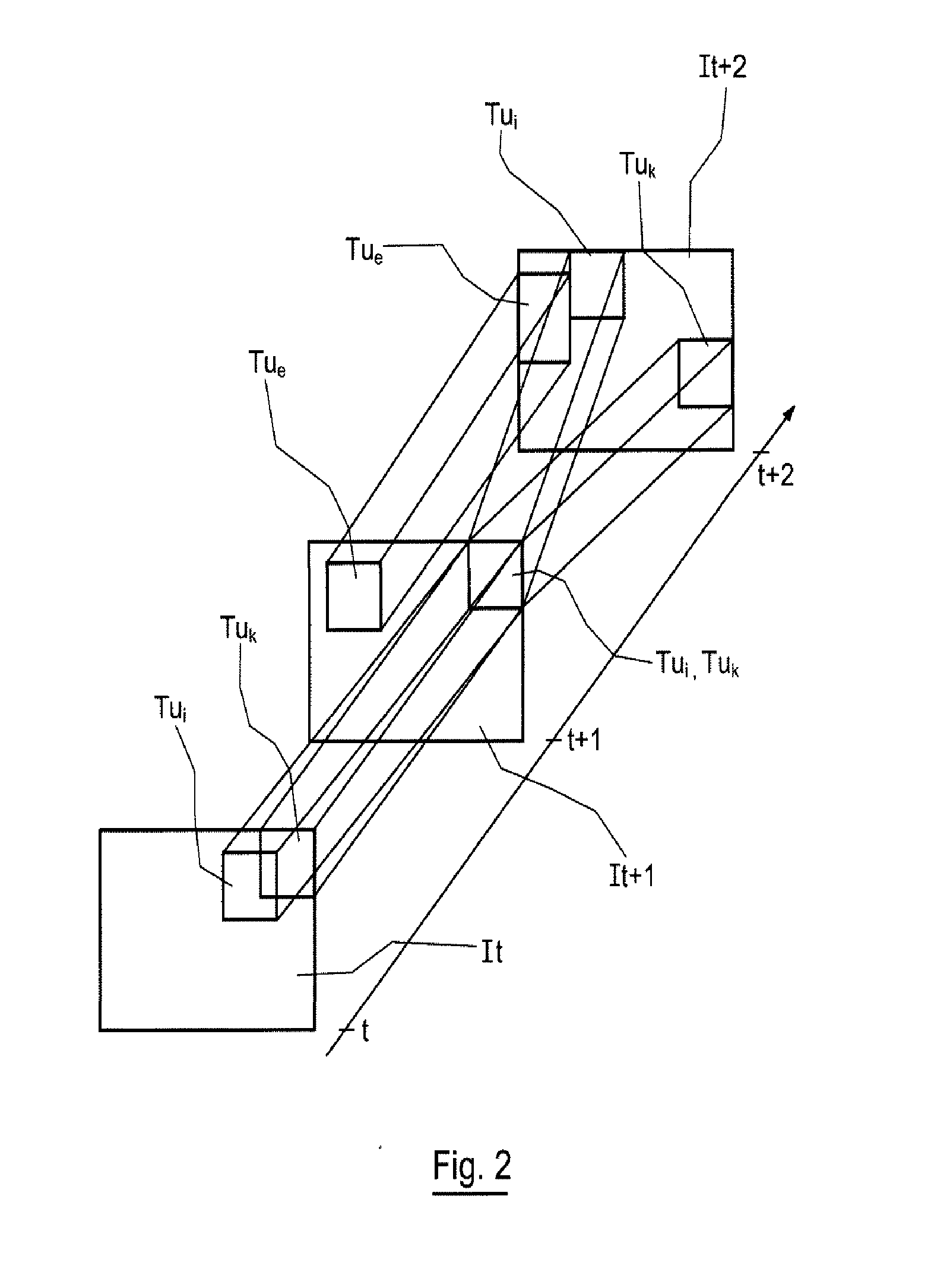
[0023]Thus, the various motion tubes can evolve independently of one another. An image sequence is then represented by a set of motion tubes moving in space over the course of time, following the motion trajectories of the sequence. This “temporal persistence” of the tubes makes it possible to represent the video sequence in a continuous manner. Moreover, this representation makes it possible to effectively represent at one and the same time the zones of continuity and discontinuity of the motion of a sequence.
[0041]According to this embodiment, the invention thus finds applications in scalable data coding and decoding, exhibiting adaptable quality and variable spatio-temporal resolution.
[0084]transition information cues, making it possible to update said reference block at least one instant t of said sequence;
[0118]transition information cues, making it possible to update said reference block at least one instant t of said sequence;said signal comprising transition information cues associated with each of said motion tubes,so as to allow, on decoding, the combining of the information cues associated with the current blocks of at least two of said tubes overlapping in an overlap zone of a current image, so as to reconstruct pixels that are optimized in the overlap zone.

Problems solved by technology

A drawback of these prior art techniques is that the blocks in each image are defined independently of the blocks of the other images of the sequence.
This gives rise to a discontinuous representation of the motion in the sequence, and therefore a poor representation of the real motion and cost overheads in terms of compression bitrate.
However, a drawback of these mesh based techniques is that the motions between the regions are constrained, and therefore do not make it possible to represent the breaks in the motion field that may arise in the image sequence (for example due to the appearances or to the disappearances of objects), between two regions having different motions.
Moreover, another drawback of these techniques stems from the use of irregular meshes, for which the structure of the mesh cells over the course of time must be transmitted.
Indeed, this transmission of additional information gives rise to penalties in terms of compression performance.

Method used


Image

  • Methods and devices for coding and decoding an image sequence represented with the aid of motion tubes, corresponding computer program products and signal
  • Methods and devices for coding and decoding an image sequence represented with the aid of motion tubes, corresponding computer program products and signal
  • Methods and devices for coding and decoding an image sequence represented with the aid of motion tubes, corresponding computer program products and signal

Examples


Embodiment Construction

1. General Principle

[0127]The general principle of an embodiment of the invention relies on the coding and the decoding of a 2D or 3D image sequence represented with the aid of motion tubes.

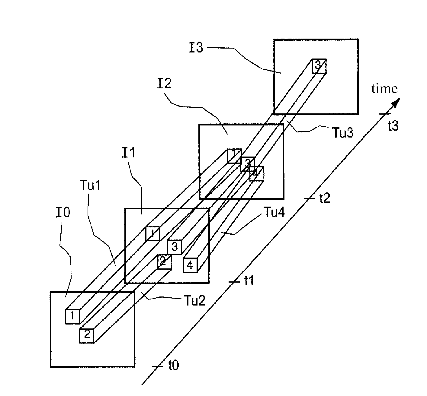
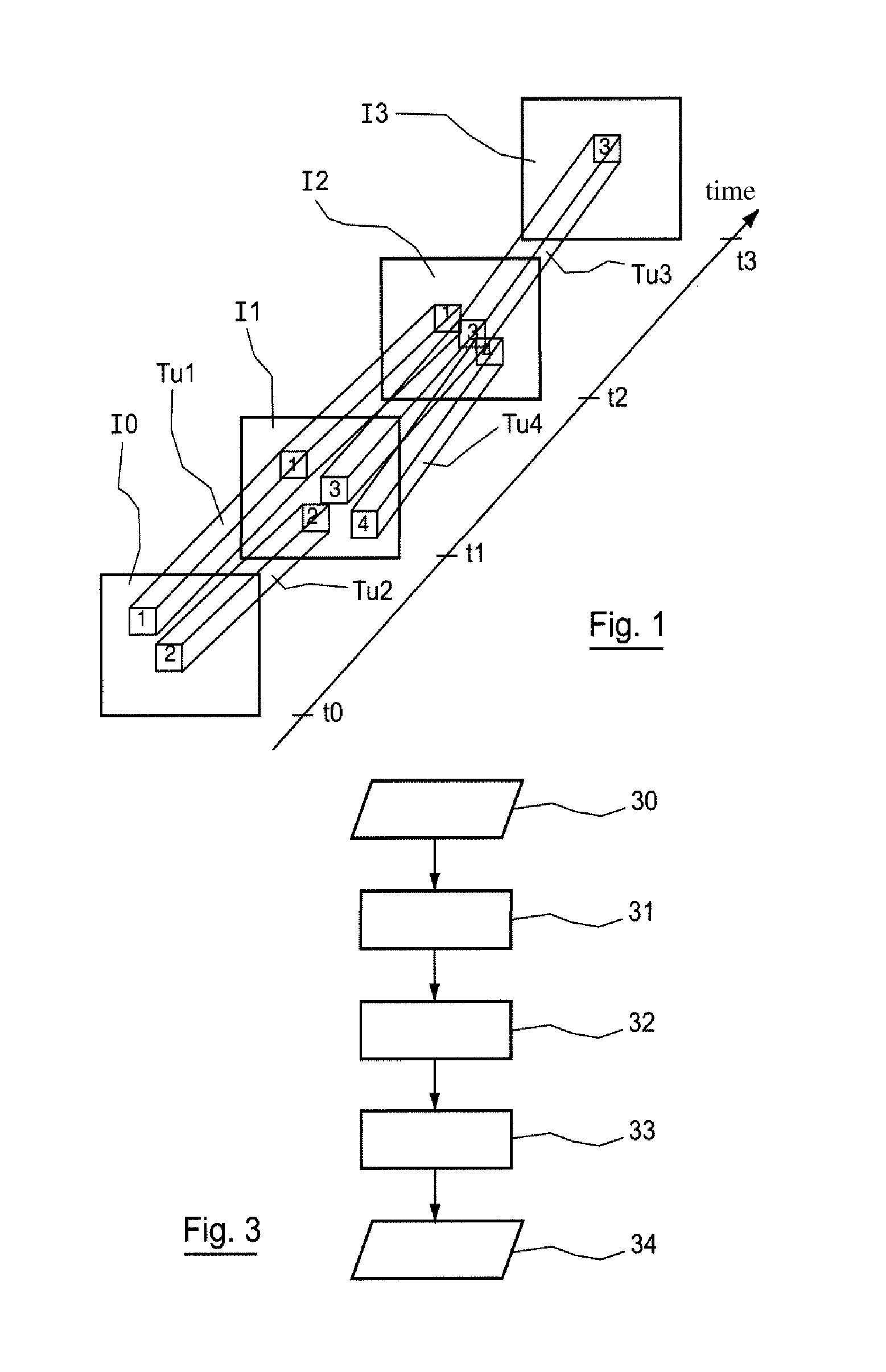
[0128]An exemplary representation of a video sequence by motion tubes is presented in relation to FIG. 1.

[0129]Four motion tubes Tu1, Tu2, Tu3 and Tu4, extending between the images I0, I1, I2 and I3, corresponding respectively to the instants t0, t1, t2 and t3 of the video sequence are considered according to this example.

[0130]More precisely, a motion tube is defined as a set of pixels (square, rectangular block, or cube in 3D for example) and its characteristics are:[0131]an instant of creation, or start-of-tube instant,[0132]an instant of disappearance, or end-of-tube instant,[0133]a set of positions (xt,yt) or of displacements (dxt,dyt) dependent on time t, t lying between the instant of creation and the instant of disappearance of the tube,[0134]a texture optionally varying over time.

[0135]F...


PUM


Abstract

A method and apparatus are provided for decoding a signal representative of an image sequence. The method includes extracting motion tubes from the signal, each of the tubes being defined by at least the following information cues: a block of reference pixels comprising reference texture information cues; start-of-tube and end-of-tube instants; and transition information cues. The method further includes processing the transition information cues and combining the information cues associated with the current blocks of at least two of the tubes overlapping in an overlap zone of the current image.

Description

CROSS-REFERENCE TO RELATED APPLICATIONS[0001]This Application is a Section 371 National Stage Application of International Application No. PCT / FR2008 / 051126, filed Jun. 23, 2008 and published as WO 2009 / 007580 on Jan. 15, 2009, not in English.STATEMENT REGARDING FEDERALLY SPONSORED RESEARCH OR DEVELOPMENT[0002]None.THE NAMES OF PARTIES TO A JOINT RESEARCH AGREEMENT[0003]None.FIELD OF THE DISCLOSURE[0004]The field of the disclosure is that of the coding and decoding of image sequences.[0005]More precisely, the disclosure relates to the processing of sequences of video images or of bidimensional or tridimensional scenes (or ones exhibiting a higher number of dimensions), represented with the aid of motion tubes.BACKGROUND OF THE DISCLOSURE[0006]Current video coders, such as developed for example in the AVC H.264 / MPEG-4 standard (“Advanced Video Coding”) of the ITU (“International Telecommunication Union”) presented in the document ISO / IEC 14496-10, make it possible to code an image se...

Claims


Application Information

Patent Timeline
IPC IPC(8): H04N7/26
CPCH04N19/553H04N19/46H04N19/17H04N19/23H04N19/29H04N19/51
Inventor PATEUX, STEPHANELE GUEN, BENJAMINCAMMAS, NATHALIEAMONOU, ISABELLEKERVADEC, SYLVAIN
Owner FRANCE TELECOM SA
Learn More