
Fluid blending apparatus and associated method

Inactive Publication Date: 2010-07-29
SARDINA JR JOSE ELIAS
View PDF5 Cites 3 Cited by
  • Summary
  • Abstract
  • Description
  • Claims
  • Application Information

AI Technical Summary

Benefits of technology

[0007]As the main fluid changes velocity, so does the turbine rotation, thus, the pump speed will adjust automatically causing the mixing fluid pumped into the main fluid to maintain constant mixing ratio.
[0016]a check valve: a check valve can be placed at the mixing fluid outlet to prevent backflow during maintenance such as replacement of the pump shaft;
[0028]1. Hand wash sinks and showers—soap bars or dispensing bottles will not be needed anymore; this can mean large savings for hotels.
[0030]3. Pet wash—This will make washing your dog, cat, or horse much easier.
[0031]4. General wash spray—Connecter to a garden hose or the inlet of a pressure washer, one will find washing much simpler.
[0032]5. Industrial tank wash—A process known as CIP can use the inventive mixer for proper chemical mixing used in the CIP process.The invention can also be utilized with other such as chlorine and water, for example, automatic chlorine additive for pool maintenance, and gasoline additives, for example, at the pump, additives can be provided for better engine care.

Problems solved by technology

Pump mixing is not practical in many applications because electricity may not be available and / or the complexity of the design and components needed make it impractical.
This method has many limitations because the vacuum effect relies on atmospheric pressure to push siphon fluid into the venturi.

Method used


Image

  • Fluid blending apparatus and associated method
  • Fluid blending apparatus and associated method
  • Fluid blending apparatus and associated method

Examples


Embodiment Construction

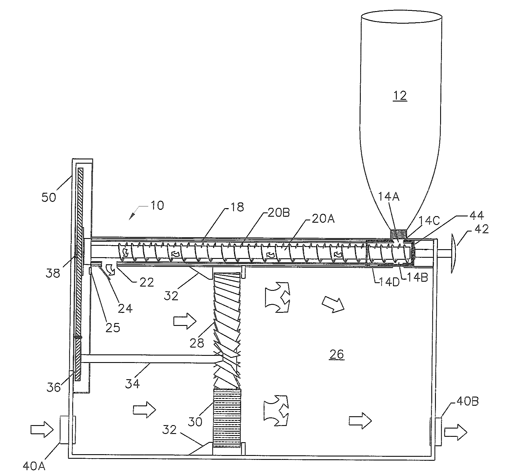
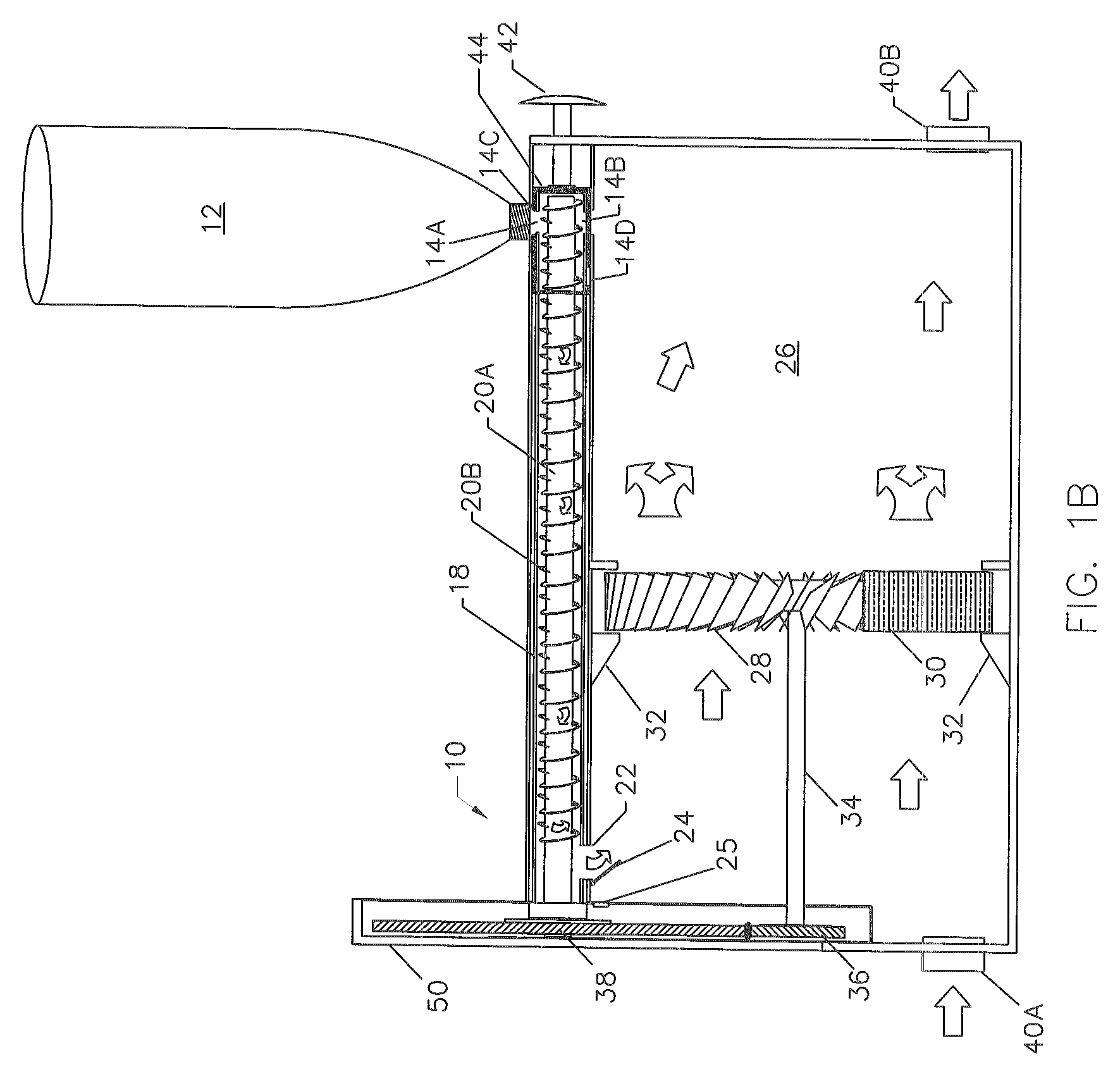
[0039]Referring now to the drawing, FIGS. 1A and 1B disclose conceptually the present invention, which is an apparatus for blending a predetermined fluid with a main fluid, and is depicted generally as 10.

[0040]The fluid blending apparatus 10 comprises a source of a predetermined fluid which is dispensable either into a fluid chamber reservoir 12 or from its own container / reservoir as depicted in FIG. 1B. If a separate reservoir is utilized, the reservoir chamber 12 has a reservoir bottom 16 on which the predetermined fluid is dispensed. Reservoir bottom 16 may or may not be inclined as desired to facilitate gravity flow to the pump assembly discussed below.

[0041]The predetermined fluid flows through a fluid inlet 14A into a pump assembly comprising a pump cylinder 18 through which a pump rotating shaft 20A rotates. The pump rotating shaft 20A further has threads 20B and is configured to form a positive displacement screw pump where the screw pump forms a main pump drive for the pre...


PUM


Abstract

An apparatus and method for blending a predetermined fluid with a main fluid wherein a source of a predetermined fluid is mixed with a main fluid. The predetermined fluid flows through an inlet of a positive displacement pump assembly and transferred to a mixing chamber through an outlet of the positive displacement pump assembly. A turbine blade assembly located within the mixing chamber is used to mix a main fluid flowing into the mixing chamber with the predetermined fluid for eventual dispensing through an outlet in the mixing chamber when desired.

Description

FIELD OF THE INVENTION[0001]The invention relates to the mixing or blending of two or more fluids at a desired ratio.BACKGROUND OF THE INVENTION[0002]Presently, fluid mixing in the contemplated fields where the invention would be useful is mainly accomplished by injecting a secondary fluid into a main fluid using an electrical pump. This means of mixing works as long as the flow remains constant and the pump speed is adjusted to supply the desired ratio of secondary fluid to main fluid. Pump mixing is not practical in many applications because electricity may not be available and / or the complexity of the design and components needed make it impractical.[0003]Another method of mixing fluids is using siphon injectors. Siphon injectors work on the fluid dynamics principle of the venturi meter. This method has many limitations because the vacuum effect relies on atmospheric pressure to push siphon fluid into the venturi. Once the vacuum pressure approaches atmospheric pressure, the maxi...

Claims


Application Information

Patent Timeline
IPC IPC(8): B01F15/04B01F25/64
CPCB01F7/00916B01F15/0416B01F15/0251B01F7/18B01F27/55B01F27/90B01F35/71775B01F35/831
Inventor SARDINA, JR., JOSE ELIAS
Owner SARDINA JR JOSE ELIAS
Learn More