
Vascular filter device

a filter device and vascular technology, applied in the field of vascular filter devices, can solve the problems of releasing clots to flow beyond the device, and achieve the effect of increasing the radial force of the capture arms

Active Publication Date: 2010-07-22
COVIDIEN GROUP +1
View PDF78 Cites 57 Cited by
  • Summary
  • Abstract
  • Description
  • Claims
  • Application Information

AI Technical Summary

Benefits of technology

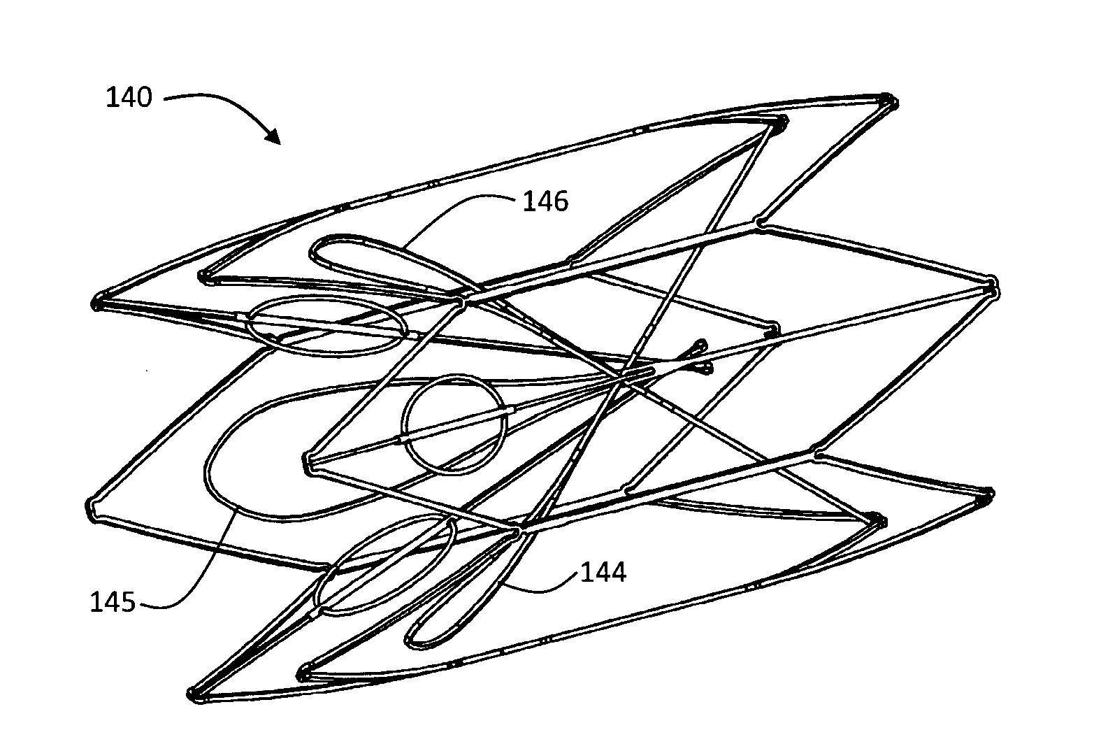
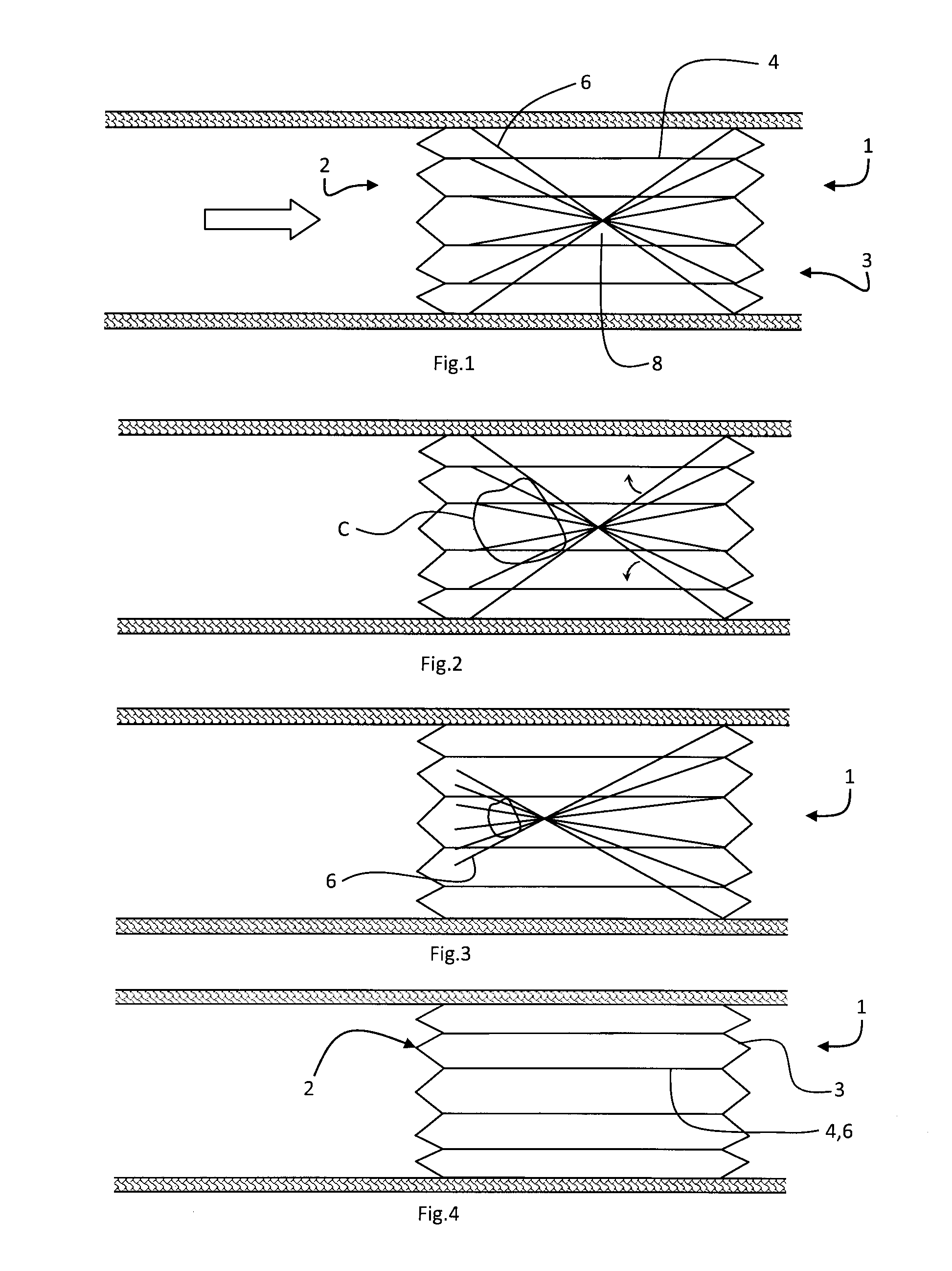
[0010]In one embodiment, said filter elements are biased towards the open state and so are pressed against a retained clot as they attempt to move to the open state, thereby aiding clot break down. In one embodiment, at least one filter element is configured to be directed radially inwardly at a proximal end when in the closed state for improved clot retention.
[0027]In one embodiment, at least one filter element is connected to the support by a holder and extends at an acute angle of less than 40° so that there is reliable conversion even with endothelial growth.
[0031]According to another aspect of the invention there is provided a vascular filter comprising: one or more capture members, the one or more capture members being configured to capture thrombus passing through a blood vessel, and the one or more capture members defining a first capture region within which thrombus may be captured. By capturing the thrombus, the filter prevents the thrombus from passing to the heart or lungs, which may cause pulmonary embolism. By supporting the capture members this ensures that the capture members are maintained in the desired location in the blood vessel.
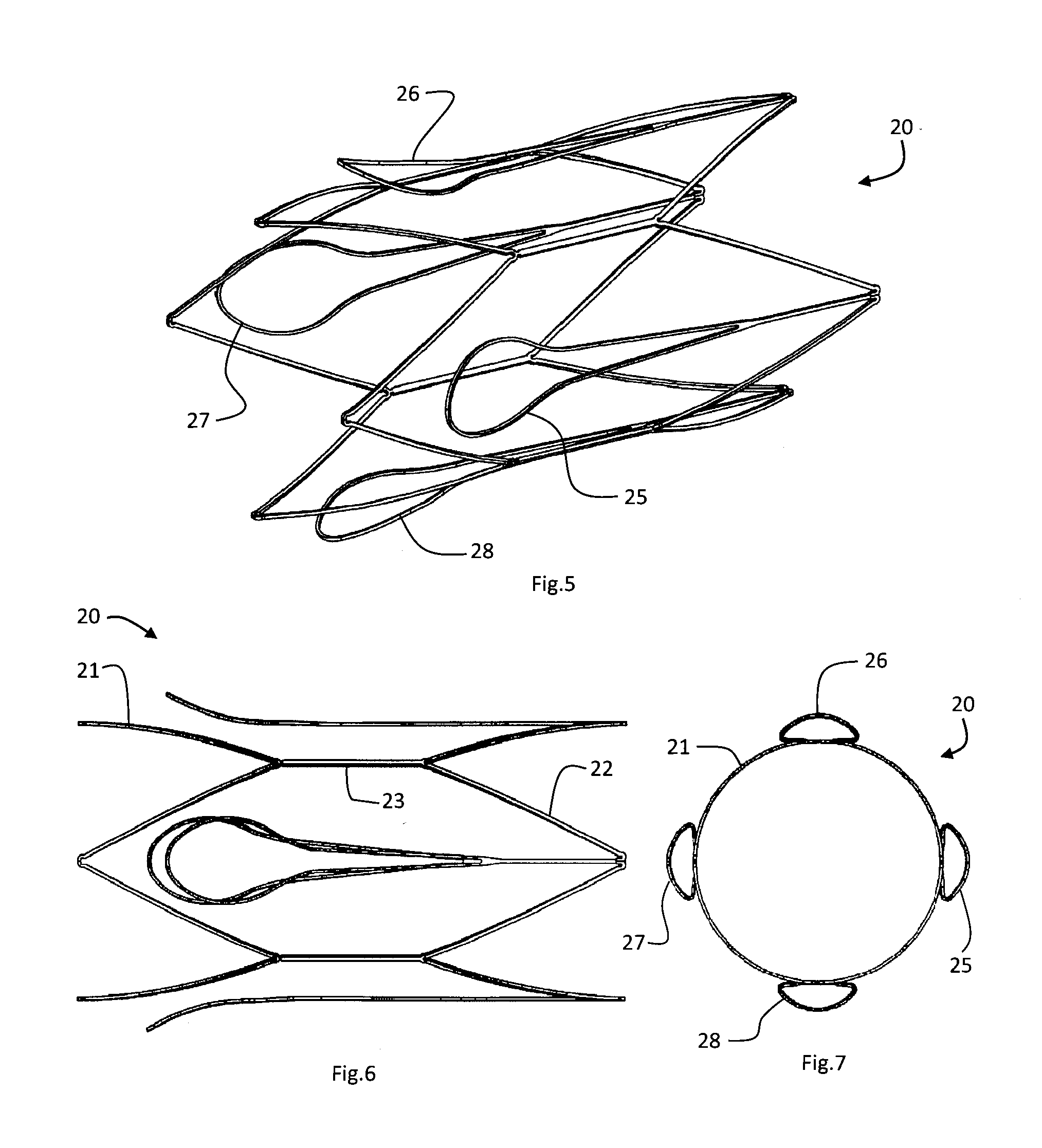
[0044]In one case the invention includes inverted capture arms. In one case the invention includes features to hold a clot from the inside of the clot. In one case the invention includes a web / trellis / membrane to a hold clot from the outside. In one case the invention increases the radial force of the capture arms.

Problems solved by technology

A problem with many devices of the convertible type is that there is a risk that a captured clot may be released to flow beyond the device upon filter conversion.

Method used


Image

  • Vascular filter device
  • Vascular filter device
  • Vascular filter device

Examples


Embodiment Construction

[0097]A vascular filter is suitable for use as an inferior vena cava filter in the inferior vena cava. In general terms the filter is movable at conversion from a capturing or closed state to an open state upon elapse of a predetermined period of time. In the capturing state the filter is configured to capture thrombus passing through the inferior vena cava towards the heart and the lungs. The filter may thus be used to prevent pulmonary embolism. In the open state the filter is configured to facilitate unrestricted blood flow.

[0098]In most of the following embodiments the filter device is deployed by collapsing for delivery, and at least partially loaded into a delivery catheter. The delivery catheter is advanced through the inferior vena cava until the collapsed filter device reaches the desired location in the inferior vena cava. A restraining sheath of the delivery catheter is then moved proximally relative to the filter to fully uncover the filter. Due to the biasing nature of ...


PUM

PropertyMeasurementUnit
acute angleaaaaaaaaaa
mechanical energyaaaaaaaaaa
stored energyaaaaaaaaaa

Abstract

A vascular filter device comprises a support; and a filter comprising one or more filter elements configured to capture thrombus passing through a blood vessel. A holder holds the filter in a closed filtering state and releases to convert the filter to an open state after a period of time. The filter is adapted to retain thrombus after said conversion. In one case the filter elements are arranged to remain in a closed state after release by the holder, because they are blocked by a retained clot from opening fully, and the filter elements are biased to the open state with a bias level which is counter balanced by force exerted by a retained clot under action of blood flow.

Description

RELATED APPLICATIONS[0001]This application claims the benefit of priority from U.S. Provisional Application No. 61 / 145,382 filed on Jan. 16, 2009, the entire contents of which are incorporated herein by reference. This application also claims the benefit of priority from U.S. Provisional Application No. 61 / 145,303 filed on Jan. 16, 2009, the entire contents of which are incorporated herein by reference.INTRODUCTION[0002]This invention relates to a vascular filter device.[0003]It is known to provide a vascular filter which is supported in a blood vessel. It includes a support, which may be stent-like. Such a device is described in our prior PCT specification no. WO2008 / 010197. Such a device has a filter comprising a number of filter elements which are held in a closed state by a holder. The holder may be biodegradable so that the filtering takes place for a limited time period which is pre-determined, say 60-90 days. Upon expiry of this time the filter converts to an open state in wh...

Claims


Application Information

Patent Timeline
Patent Type & Authority Applications(United States)
IPC IPC(8): A61B17/22
CPCA61F2/01A61F2002/016A61F2210/0004A61F2250/0059A61F2230/0078A61F2230/0058A61F2230/006A61F2230/0067A61F2230/005
Inventor HORAN, STEVENGILSON, PAULKEATING, KARLHENRY, JEROMEO'GORMAN, JACQUELINEO'CONNOR, RONANMOLLOY, SHANE
Owner COVIDIEN GROUP
Learn More