
Vehicle interior state recognition device

a recognition device and interior technology, applied in the field of vehicle interior state recognition devices, can solve the problems of inaccurate passenger detection, insufficient inflation control of airbags, and inability to accurately determine etc., and achieve the effect of accurately determining the size of passengers sitting in seats

Inactive Publication Date: 2010-07-22
MAZDA MOTOR CORP
View PDF14 Cites 22 Cited by
  • Summary
  • Abstract
  • Description
  • Claims
  • Application Information

AI Technical Summary

Benefits of technology

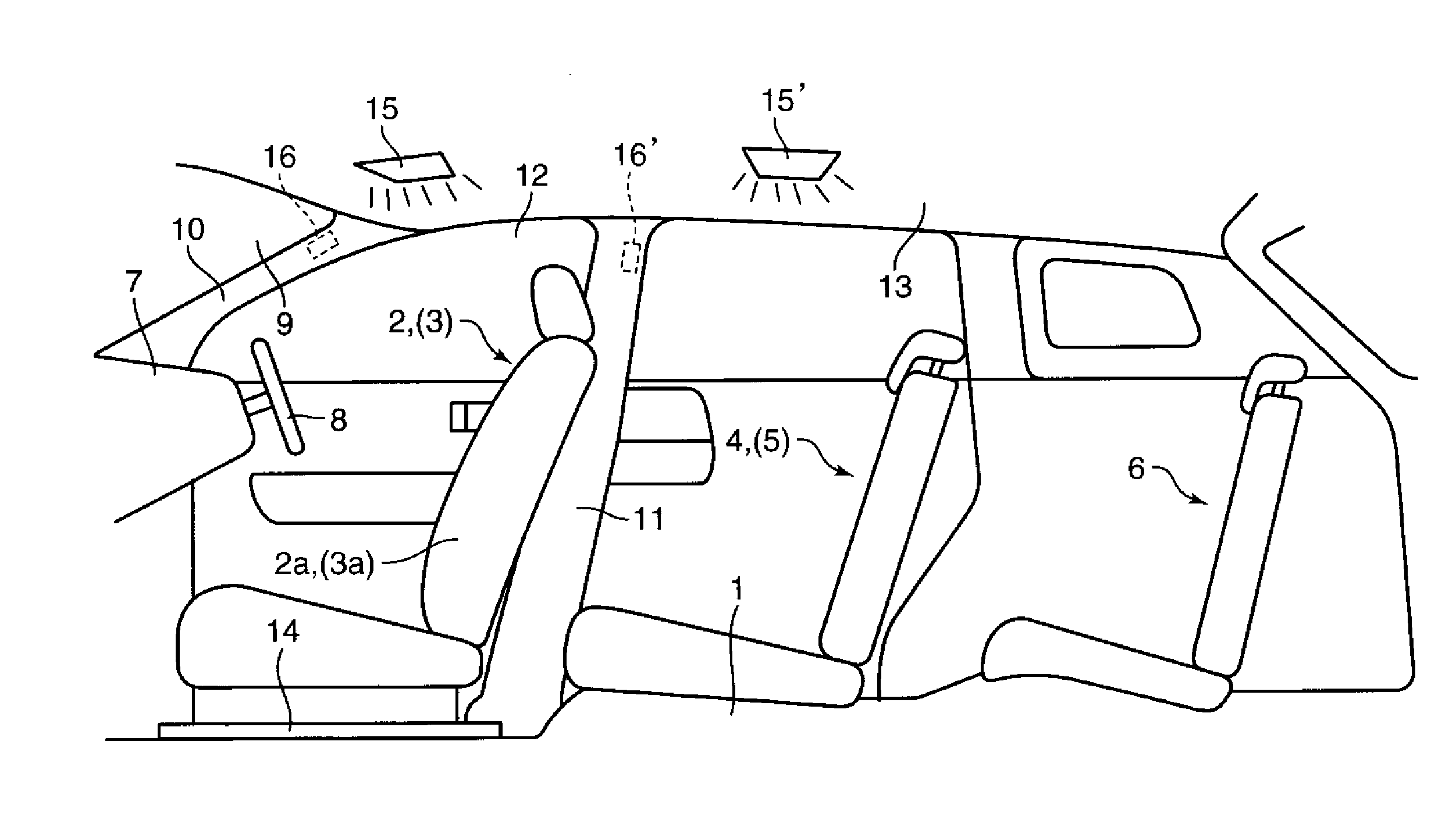
The present invention provides a vehicle interior state recognition device that can accurately determine the size of a passenger seated in a seat and the positional relationship between the seat and the passenger. This is achieved by comparing the contour of the seat with the contour of the passenger on an image picked up by infrared rays. The device can be used in airbag-inflation control to ensure safety at vehicle crashes. The seats can be equipped with a headrest, and the device can accurately determine the height of the headrest relative to the passenger. This helps to maintain safety standards during a rear crash.

Problems solved by technology

Herein, in case the pressure sensor or the strain sensor are provided as described above, there is a concern that the detection of passenger would become inaccurate due to fluctuations of detections of the sensor which may be caused by position changes of the passenger, vehicle's vibrations during traveling or the like.
Further, even if the detection of the passenger is detected, the size of the passenger may not be detected.
Accordingly, there is a concern that the inflation control of airbag would not be properly executed.
For example, if the airbag was inflated forcibly despite the child having a relatively small body size, the safety of the passenger would be rather deteriorated.
However, in case the seat is provided to be movable relative to a vehicle body, the distance between the image pick-up device and an object, an image of which is to be picked up, may change depending on the seat's position, so that the detected size of the passenger or the like may also change improperly despite the same passenger.
Accordingly, there is a problem in that the size of the passenger seated in the seat or a positional relationship between the seat and the passenger seated in the seat would not be accurately determined

Method used


Image

  • Vehicle interior state recognition device
  • Vehicle interior state recognition device
  • Vehicle interior state recognition device

Examples


embodiment 1

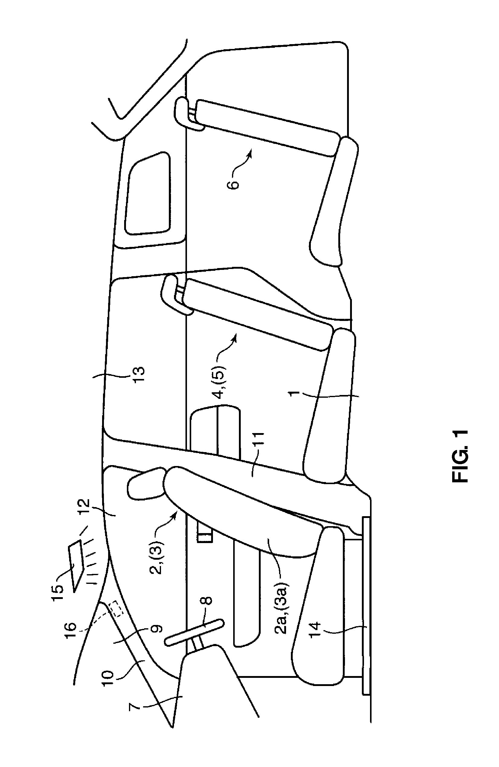
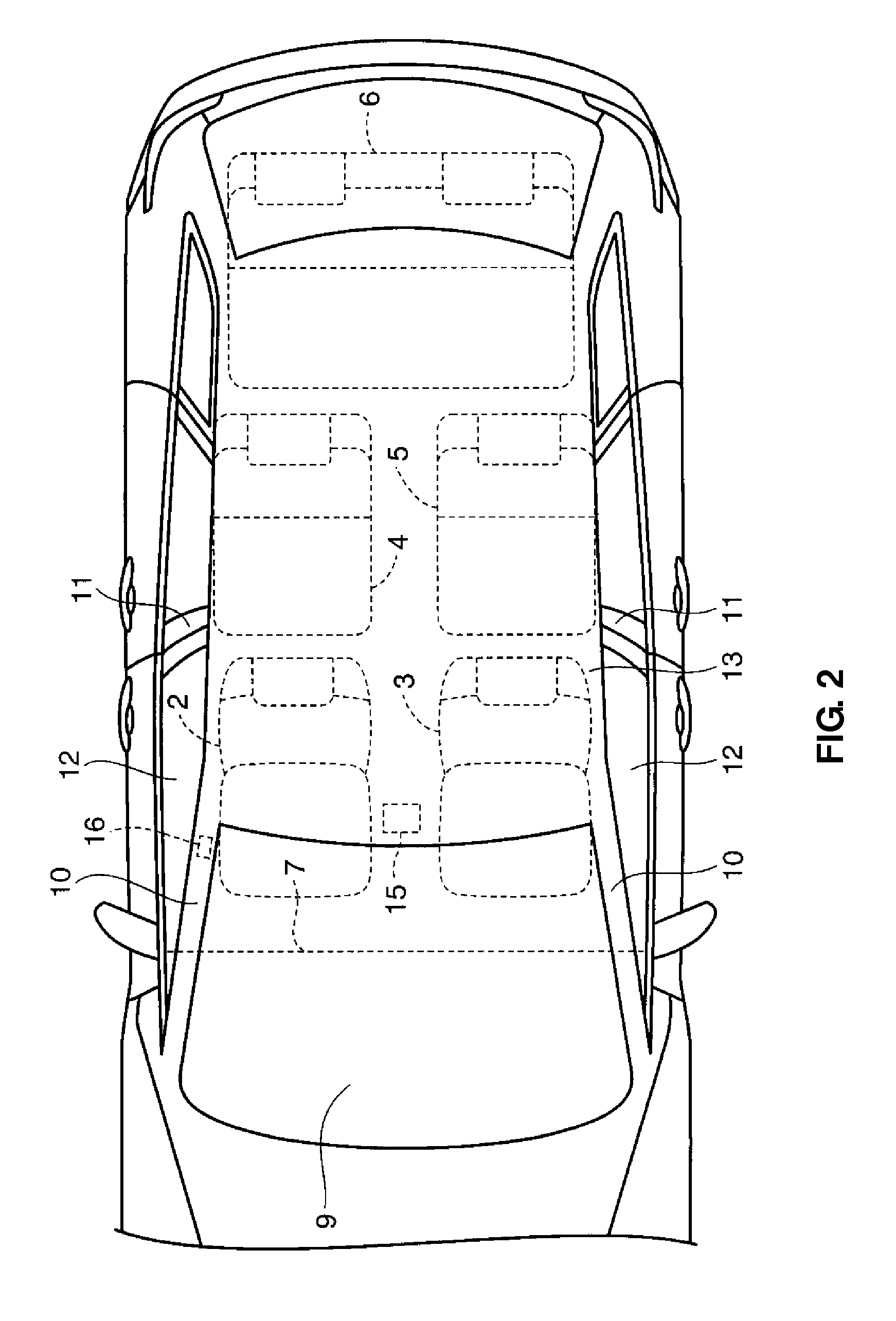
[0059]FIGS. 1 through 3 show a whole constitution of a vehicle to which a vehicle interior state recognition device according to a first embodiment of the present invention is applied. The vehicle illustrated in these figures is a so-called minivan type of automotive vehicle which has in total three rows of seats on a vehicle floor 1. Specifically, a driver's seat 2 and a passenger's seat 3 are provided at a front portion on the vehicle floor 1, and behind these seats are provided first separate rear seats 4, 5 and a second integral rear seat 6 (a so-called bench type seat). The driver's seat 2 and the passenger's seat 3 are supported to be moveable longitudinally along seat slide rails 14 which are arranged on the vehicle floor 1.

[0060]An instrument panel 7 which extends in a vehicle width direction is provided in front of the driver's seat 2 and the passenger's seat 3. A steering wheel 8 is arranged at a portion of the instrument panel 7 on the side of the driver's seat 2. A winds...

embodiment 2

[0103]A second embodiment will be described referring to FIGS. 12 through 18. According to the second embodiment, a recognizing means 18′ further determines the height of a headrest relative to the passenger seated in the seat based on an image of the headrest which is picked up by the image pick-up means 16, in addition to the determination functions described in the above-described first embodiment. Hereinafter, the same constitutions of the second embodiment as those of the first embodiments are denoted by the same reference characters, detailed descriptions of which are omitted here.

[0104]At upper portions of seatbacks 41, 42 of the driver's and passenger's seats 2, 3 are provided headrests 51, 52 to support rear head portions of the passengers. These headrests 51, 52 are supported at the seatbacks 41, 42 via slide poles K1 which slide vertically relative to the seatbacks 41, 42 (FIG. 12). The heights of the headrests 51, 52 are respectively adjustable within a specified range b...

embodiment 3

[0123]A third embodiment will be described referring to FIGS. 19 through 27.

[0124]A vehicle A comprises seats S1a, S1b (first seats) which are disposed side by side in a vehicle compartment, seats S2a, S2b (second seat) which are disposed in back of the seats S1a, S1b, seats S3a, S3b, S3c which are disposed in back of the seats S2a, S2b, and a restraint portion B in which passengers seated in the seats are restrained.

[0125]The seat S1a is a driver's seat, and the seat S1b is a passenger's seat. The seats S2a, S2b are a second row seat for two passengers. The seats S3a, S3b, S3c are a third row seat which comprises a so-called bench seat for two passengers and a single seat for one passenger. Each of the seats has a longitudinally-moving mechanism (slide mechanism) and an inclination mechanism (reclining mechanism) which inclines a seatback thereof around its lower end portion longitudinally. Herein, while the present embodiment will be described in such a manner that the first row s...


PUM


Abstract

A vehicle interior state recognition device comprises an illuminating means for illuminating infrared rays into a vehicle compartment, an image pick-up means for picking up an image inside the vehicle compartment into which the infrared rays are illuminated by the illuminating means, and a recognizing means for recognizing specified information based on the image picked up by the image pick-up means. Objects of the image picked up by the image pick-up means include a seat which is movable relative to a vehicle body and a passenger seated in the seat, and the recognizing means determines a size of the passenger by comparing contour of the seat with contour of the passenger on the image picked up. Accordingly, the body size of the passenger seated in the seat can be determined accurately.

Description

BACKGROUND OF THE INVENTION[0001]The present invention relates to a vehicle interior state recognition device which comprises an illuminating means for illuminating infrared rays into a vehicle compartment, an image pick-up means for picking up an image inside the vehicle compartment into which the infrared rays are illuminated by the illuminating means, and a recognizing means for recognizing specified information based on the image picked up by the image pick-up means.[0002]Conventionally, the detection of an existence of any passenger who is seated in a seat has been conducted in order to determine the necessity of inflation of an airbag, for example. According to a well known art, there are provided a pressure sensor or a strain sensor at a seat face, which detect whether the passenger is seated in the seat or not.[0003]Herein, in case the pressure sensor or the strain sensor are provided as described above, there is a concern that the detection of passenger would become inaccur...

Claims


Application Information

Patent Timeline
Patent Type & Authority Applications(United States)
IPC IPC(8): H04N7/18B60R21/16
CPCB60N2/002G06K9/00362G06K9/00832G06T7/60G06T2207/30268B60R21/01538B60R21/01544G06V40/10G06V20/59B60N2/0028B60N2/0023B60N2210/18
Inventor SAKAKIDA, MASAFUMITOMITA, TOSHIHIKOYAMANISHI, MITSUTOSHIYAMANE, KEIKOHARADA, TSUKASAHAYASHI, KAZUHITO
Owner MAZDA MOTOR CORP
Learn More