
Pressure measuring syringe

a technology of pressure measuring and syringe, which is applied in the direction of manufacturing tools, instruments, catheters, etc., can solve the problems of mucosal ulceration, scarring and rupture of the trachea, over-inflated cuffs, and other serious conditions

Inactive Publication Date: 2010-07-15
BETH ISRAEL DEACONESS MEDICAL CENT INC +1
View PDF22 Cites 95 Cited by
  • Summary
  • Abstract
  • Description
  • Claims
  • Application Information

AI Technical Summary

Benefits of technology

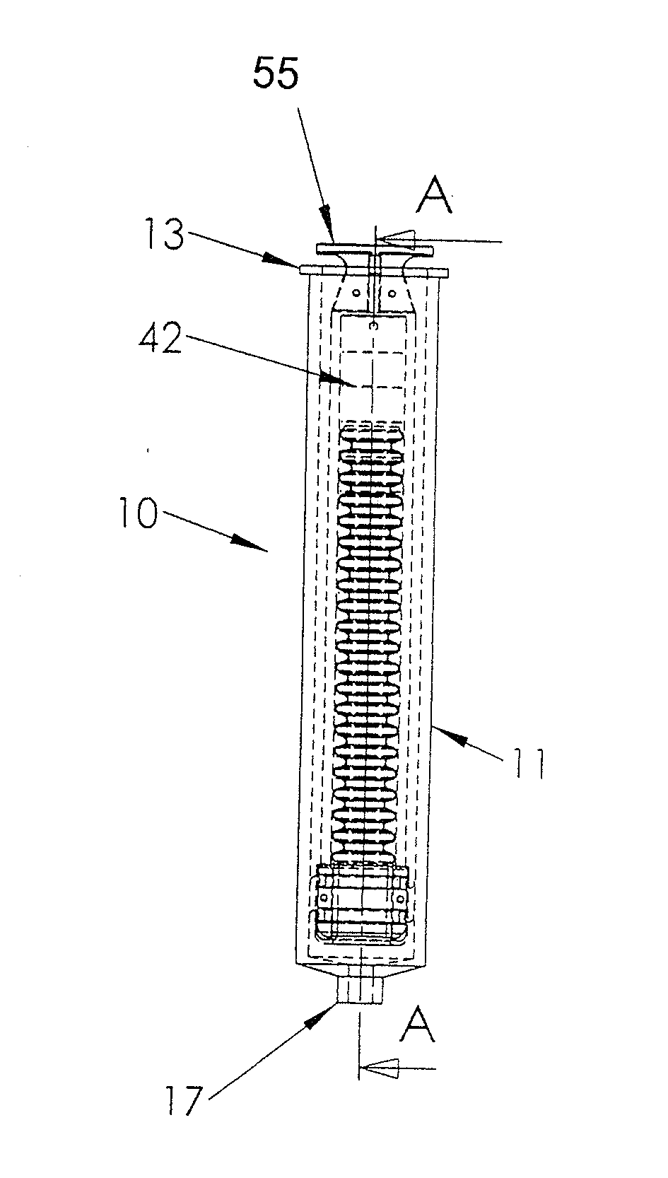
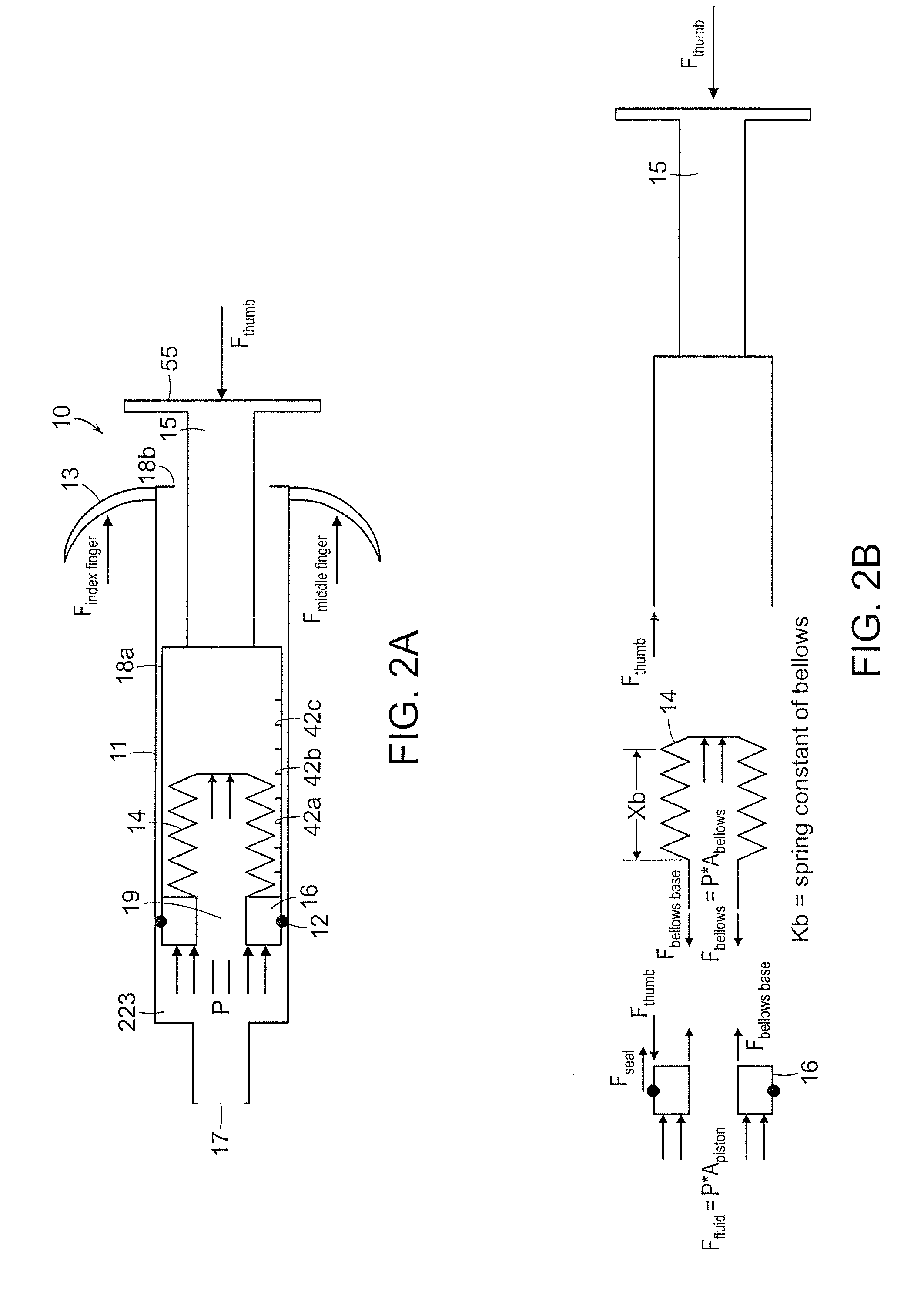
[0008]The present invention relates to a pressure measuring syringe. A preferred embodiment utilizes a spring mounted to a syringe plunger that is displaced by the fluid pressure in the distal chamber of the syringe. A preferred embodiment mounts a spring in the form of a flexible diaphragm or bellows to the plunger of the syringe that reduces the friction of the system to provide a more accurate measurement of fluid pressure, particularly at lower pressures.
[0010]According to one aspect of the present invention, a syringe having an internal pressure gauge comprises a barrel having an aperture at a tip end and an opening at an opposed end; a plunger or piston arranged within the barrel and forming a seal against an internal wall of the barrel to define a fluid chamber proximate the plunger. A spring, flexible diaphragm or bellows arranged within the barrel is axially movable within the piston. The spring, flexible diaphragm or bellows operates as a moveable pressure indicator and can be mounted at a first end to the plunger and is free to move at a second end. The pressure indicator, such as a spring, can be calibrated to provide a resistance force against the axial movement that is indicative of a pressure within the fluid chamber. Visual indicia are used to indicate the pressure within the fluid chamber based on the relative position of the spring, the visual indicia indicating gas pressures within a range between a lower pressure limit and an upper pressure limit, or approximately from 5 to 35 cm H2O. The fluid chamber can be in fluid communication with a cuff of an endotracheal tube, such that the measured pressure comprises the fluid pressure within the cuff. As the end of the spring or bellows is free to move without any substantial friction against the inner tubular wall of the plunger, it can more accurately reflect the gas pressure in the syringe chamber. The proximal end or second portion of the spring is thus mechanically decoupled from the inner wall of the plunger and consequently operates without the use of a seal. The distal end of the spring (or first portions) is coupled to the plunger in such a way that a seal is formed between the outer peripheral surface of a portion of the plunger and inner wall of the syringe barrel so that displacement of the plunger will displace fluid through the distal opening of the syringe.
[0012]According to another aspect, a method of measuring the pressure within a cuff of an endotracheal tube comprises providing a syringe in accordance with the invention in fluid communication with the cuff, actuating the syringe by depressing the plunger relative to the barrel, and detecting the visual indicia to measure the pressure inside the cuff. For circumstances involving longer term use, such as with a ventilator, it is desirable to monitor the pressure in the cuff, however, in certain cases it is not desirable to maintain a syringe adjacent to the patient's mouth. The syringe can be marked with a reattachment location for the plunger whereby the user can connect the syringe to the port or inlet valve whereby opening the valve will not significantly alter the pressure existing in the cuff and enable the measurement of the current cuff pressure. This enables periodic reconnection and measurement of cuff pressure without the need to completely reinflate the cuff. Preferably, the seal between the plunger and the outer wall of the syringe is sufficient to hold the plunger in place after the user releases pressure, thereby permitting an ongoing measurement of pressure.

Problems solved by technology

Other catastrophic complications of an over-inflated cuff include mucosal ulceration, perforation, scarring and rupture of the trachea, and fistula.
Consequences of an under-inflated cuff include not only air leakage around the tube, but also serious complications such as silent aspiration of secretions and other foreign material, which can lead to pneumonia and other serious conditions.
Furthermore, unsafe cuff pressures can develop in an intubated patient over time.
Leaks in the cuff or elsewhere in the ETT can result in a gradual pressure loss, and absorption by the cuff of certain gases, such as nitrous oxide, can actually increase cuff pressure during intubation.
Thus, the cuff pressure cannot be reliably controlled by simply maintaining a pre-determined volume of air within the cuff.
This technique has been demonstrated to be highly inaccurate.
Syringe employed to inflate the cuff have been adopted to measure pressure but have failed to provide the sensitivity and range for reliable cuff pressure measurement.
However, manometers are bulky, expensive devices that are typically not used nor readily available at the point-of-care.
Furthermore, these devices are not always accurate, since many pressure gauges add compressible volume which can affect measurement and can even negatively effect cuff pressure as a result of the measurement.

Method used


Image

  • Pressure measuring syringe
  • Pressure measuring syringe
  • Pressure measuring syringe

Examples


Embodiment Construction

[0036]This application claims the benefit of U.S. Provisional Application No. 61 / 144,956, filed Jan. 15, 2009, the entire teachings of which are incorporated herein by reference.

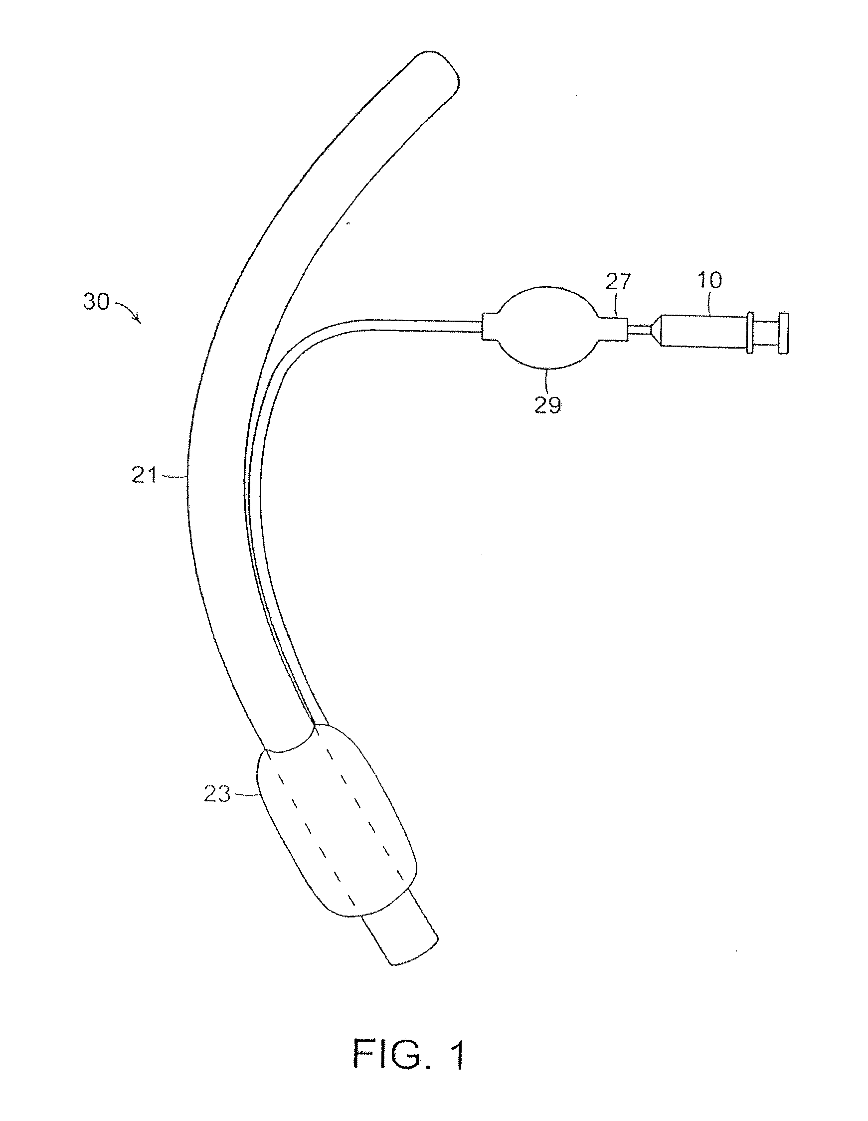
[0037]The invention comprises a syringe 10 having an internal pressure gauge, and can be used in connection with an endotracheal tube assembly 20, such as is schematically illustrated in FIG. 1. The endotracheal tube assembly 20 includes an elongated tubular member 21 that can be inserted into the windpipe (trachea) of a patient to provide an open air passageway to and from the patient's lung(s). Typically, the tube assembly 20 comprises an inflatable cuff 23 near the distal end of the tubular member 23. The cuff 23 is generally in an un-inflated state when the assembly 20 is introduced into the patient's trachea. The cuffs currently in use are referred to as high volume and low pressure, such as those manufactured by Portex, Ltd., Hythe, U.K. The cuff volume can be in the range of 15 to 20 cc when fully inf...


PUM

PropertyMeasurementUnit
thicknessaaaaaaaaaa
volumeaaaaaaaaaa
volumeaaaaaaaaaa

Abstract

A syringe having an internal pressure gauge comprises a syringe barrel; a piston within the barrel; a spring coupled to the piston at a first position of the spring, the spring having a second portion that is movable in response to fluid pressure within a syringe cavity; and a pressure gauge having an indicator correlated to a plurality of positions of the second portion of the spring to indicate a pressure of a fluid. The spring can be a bellows. The first portion of the spring can be coupled to the piston to form a sliding seal with an inner wall of the syringe, and the second portion of the spring can move longitudinally within the syringe without sealing contact. The syringe can indicate fluid pressures within a range of at least about 5 to 35 cm H2O, for example. The fluid chamber can be in fluid communication with a cuff of an inflatable medical device, such as an endotracheal tube, such that the measured pressure comprises the fluid pressure within the cuff. Methods of measuring pressure using a syringe are also disclosed.

Description

CROSS-REFERENCE TO RELATED APPLICATIONS[0001]This application claims the benefit of U.S. Provisional Application No. 61 / 144,956, filed Jan. 15, 2009.BACKGROUND OF THE INVENTION[0002]An endotracheal tube (ETT) is commonly used in medical procedures, such as during anesthesia, intensive care, and emergency care, to provide an open airway to the patient's lungs, as may be required, for example, for mechanical ventilation. The ETT is inserted into the patient's trachea, in a process known as intubation, and typically a balloon-like cuff near the distal end of the tube is inflated to secure the tube within the trachea and prevent leaks around the tube.[0003]When intubating a patient, it is important to avoid over-inflation of the cuff, since excessive cuff pressure against the tracheal wall can cause mucosal ischemia, and the subsequent pressure necrosis can lead to tracheal stenosis. Other catastrophic complications of an over-inflated cuff include mucosal ulceration, perforation, scarr...

Claims


Application Information

Patent Timeline
Patent Type & Authority Applications(United States)
IPC IPC(8): A61M5/32B23P17/04G01L7/06A61F2/958
CPCA61M25/1018Y10T29/49826A61M16/044A61M25/10182
Inventor SPIEGEL, JOAN E.SLOCUM, ALEXANDER H.
Owner BETH ISRAEL DEACONESS MEDICAL CENT INC
Learn More