
Electric shaver

a shaving device and electric technology, applied in the direction of metal working devices, etc., can solve the problems of increasing manufacturing costs and complicated overall structure, and achieve the effects of increasing the number of components, increasing manufacturing costs, and complex overall structur

Inactive Publication Date: 2010-07-15
PANASONIC CORP
View PDF11 Cites 11 Cited by
  • Summary
  • Abstract
  • Description
  • Claims
  • Application Information

AI Technical Summary

Benefits of technology

[0006]In the conventional electric shaver, however, a lock switch and a switching knob are provided as separate members in the gripper portion. Here, the lock switch is configured to lock the head portion configured to swing in the anteroposterior directions with respect to the gripper portion. The switching knob is configured to switch the edge-trimmer-blade unit between the ready-for-use state and the stored state. Providing the lock switch and the switching knob as separate members increases the number of component parts, makes the overall structure more intricate, and raises the manufacturing cost.
[0007]An object of the present invention, made to solve the above-mentioned problem, is to provide an electric shaver not needing a switch to lock the head portion, thereby reducing the number of component parts, simplifying the overall structure, and reducing the manufacturing cost.

Problems solved by technology

Providing the lock switch and the switching knob as separate members increases the number of component parts, makes the overall structure more intricate, and raises the manufacturing cost.

Method used


Image

  • Electric shaver
  • Electric shaver
  • Electric shaver

Examples


first embodiment

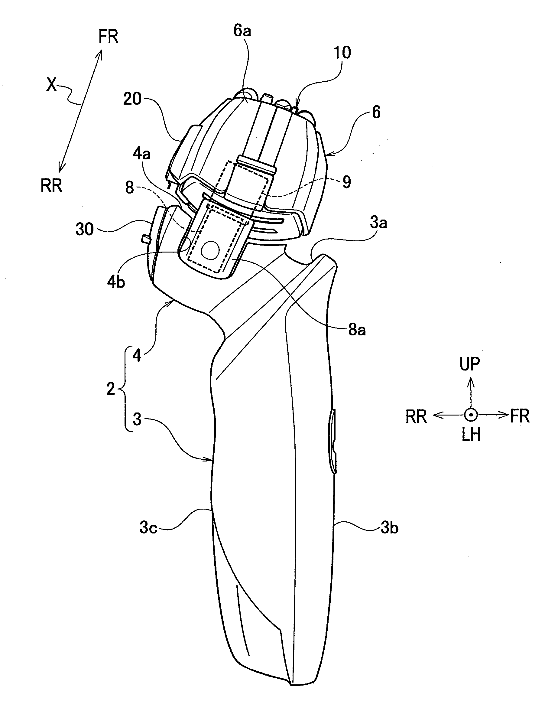
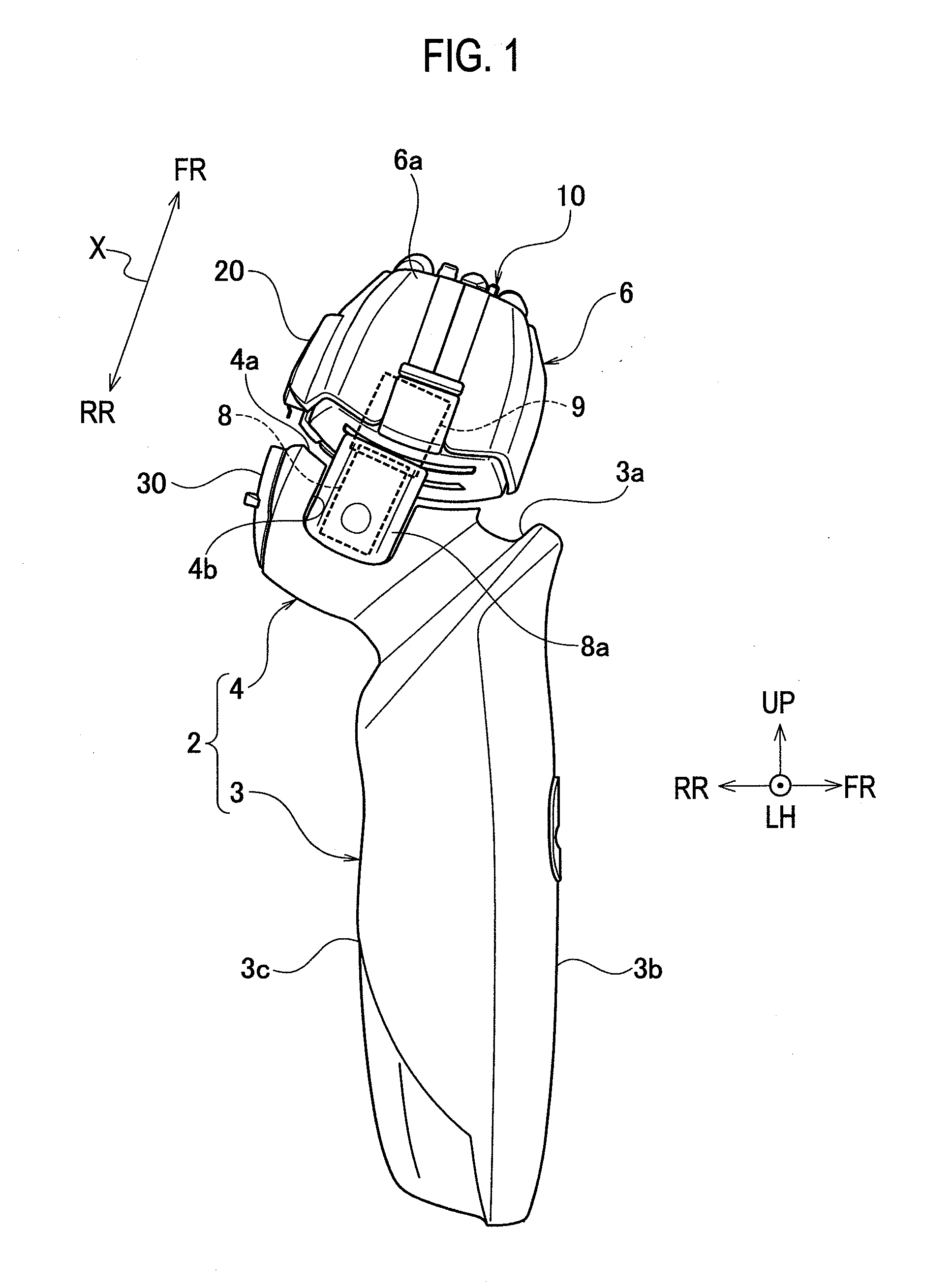
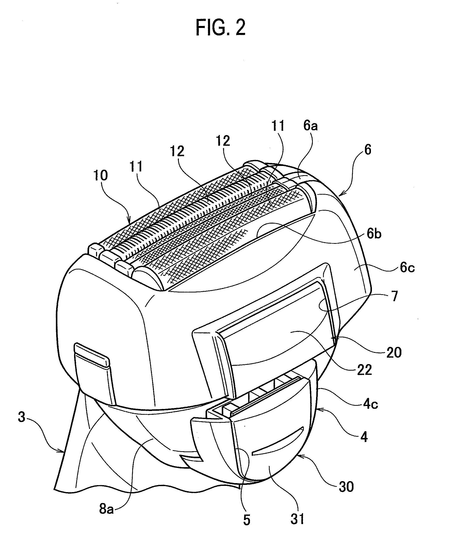
[0026]As FIGS. 1 and 15 show, an electric shaver 1 according to the present invention includes a gripper portion 2 and a head portion 6. The gripper portion 2 is the portion that the user grips with his / her hand. The head portion 6 holds a shaving-blade unit 10 and is supported by the gripper portion 2 in such a manner as to be swingable in the anteroposterior directions and / or in the lateral directions with respect to the gripper portion 2.

[0027]The gripper portion 2 includes a gripper main body 3 and a gripper connecting portion 4. The gripper main body 3 is made of a synthetic resin, and includes a front-side surface 3b, a back-side surface 3c, and an upper-side surface 3a. The upper-side surface 3a slopes downwards from the front-side surface 3b to the back-side surface 3c. The gripper connecting portion 4 is made of a synthetic resin, and protrudes obliquely upwards to the rear from the upper-side surface 3a of the gripper main body 3.

[0028]A recessed portion 4b is formed at th...

second embodiment

[0047]FIG. 16 is a perspective view illustrating a principal portion of an electric shaver according to the present invention.

[0048]The second embodiment differs from the first embodiment in that an operation element 30′ configured to switch the state of the edge-trimmer-blade unit 20 between the ready-for-use state and the stored state is provided in the head portion 6. The other portions in the configuration of the second embodiment are identical to their respective counterparts in the configuration of the first embodiment. So, the same reference numerals as those used in the first embodiment are given to the identical constituent portions in the second embodiment, and no detailed description for the identical portions will be given.

[0049]In this second embodiment, the operation element 30′ configured to switch the state of the edge-trimmer-blade unit 20 between the ready-for-use state and the stored state is provided in the head portion 6. Accordingly, there is no operation porti...


PUM


Abstract

An electric shaver including: a gripper portion to be held by the user's hand; and a head portion configured to hold a shaving-blade unit and supported to be swingable in predetermined directions with respect to the gripper portion, wherein the head portion is provided with: an edge-trimmer-blade unit configured to be switched between a ready-for-use state and a stored state by an operation element; and a engaging portion for fixing the head portion, the engaging portion configured to be engaged with the operation element when the edge-trimmer-blade unit is switched to the ready

Description

BACKGROUND OF THE INVENTION[0001]1. Field of the Invention[0002]The present invention relates to an electric shaver in which a head portion holding a shaving-blade unit including an inner blade and an outer blade is supported to be swingable in predetermined directions with respect to a gripper portion.[0003]2. Description of the Related Art[0004]Japanese Patent Application Publication No. 2002-315978 discloses an electric shaver of the above-mentioned kind, which includes not only a shaving-blade unit including an inner blade and an outer blade but also an edge-trimmer-blade unit.[0005]The electric shaver includes a gripper portion to be held by the user's hand and a head portion configured to hold the shaving-blade unit, and supported to be swingable in the anteroposterior directions with respect to the gripper portion. Moreover, the electric shaver includes the edge-trimmer-blade unit in an upper-side portion on the back-side surface of the gripper portion. A switching knob is pr...

Claims


Application Information

Patent Timeline
Patent Type & Authority Applications(United States)
IPC IPC(8): B26B19/00B26B19/28
CPCB26B19/105B26B19/048
Inventor SHIGETA, HIROSHIYAMASAKI, MASANOBUHOSOKAWA, SHINSHIBA, TAKESHIIWASAKI, JYUZAEMON
Owner PANASONIC CORP
Learn More