Zoom lens and image capture apparatus

Inactive Publication Date: 2010-07-08
SONY CORP
View PDF2 Cites 16 Cited by
  • Summary
  • Abstract
  • Description
  • Claims
  • Application Information

AI Technical Summary

Benefits of technology

[0018]Further, in the zoom lens, the surface closest to the object side in the second lens group is aspheric. Thereby, the zoom lens is able to correct spherical aberration and coma aberration satisfactorily. As a result, the zoom lens has an advantage in that it is easy to obtain a reliable optical performance even when a high magnification power and a wide angle of the optical system are achieved.
[0065]The zoom lens provided in the image capture apparatus with such a configuration is suitable for an image capture apparatus using a solid-state image pickup device as image pickup means while achieving a wide angle and a high zoom ratio, being compact, and having a high optical performance in the entire zoom range.

Problems solved by technology

Nowadays, there has not yet been invented a zoom lens which is capable of achieving both a high magnification ratio and a wide angle and which has a small size and a high image quality.
Further, similarly to the zoom lens having the three-group configuration disclosed in Japanese Unexamined Patent Application Publication No. 2006-78581 mentioned above, most of the lenses have a zoom ratio of three times or so, and it is hard for the lenses to achieve a sufficient zoom ratio above that.

Method used


Image

  • Zoom lens and image capture apparatus
  • Zoom lens and image capture apparatus
  • Zoom lens and image capture apparatus

Examples


embodiment

1. Embodiment

1-1. Configuration of Zoom Lens

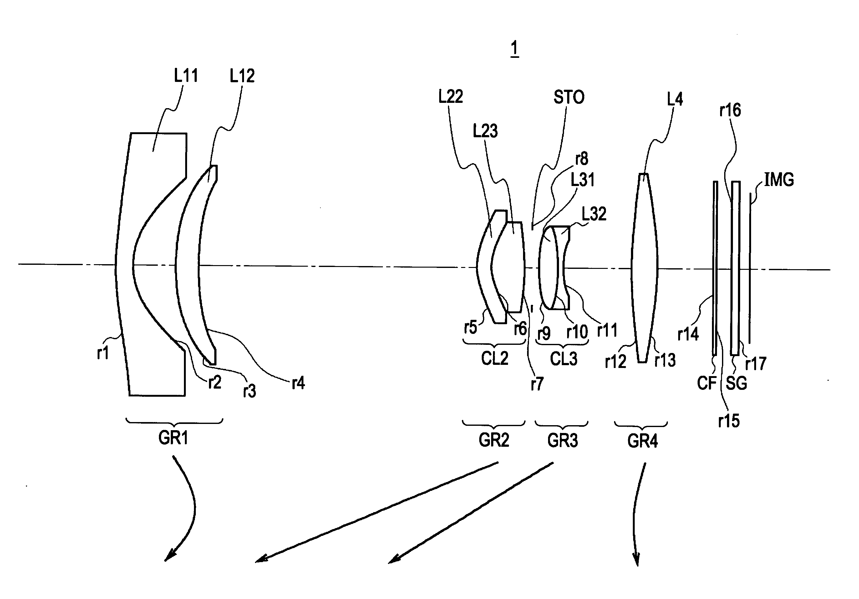
[0083]A zoom lens according to an embodiment of the invention includes, in order from the object side: a first lens group with a negative focal length; a second lens group with a positive focal length; a third lens group with a negative focal length; and a fourth lens group with a positive focal length.

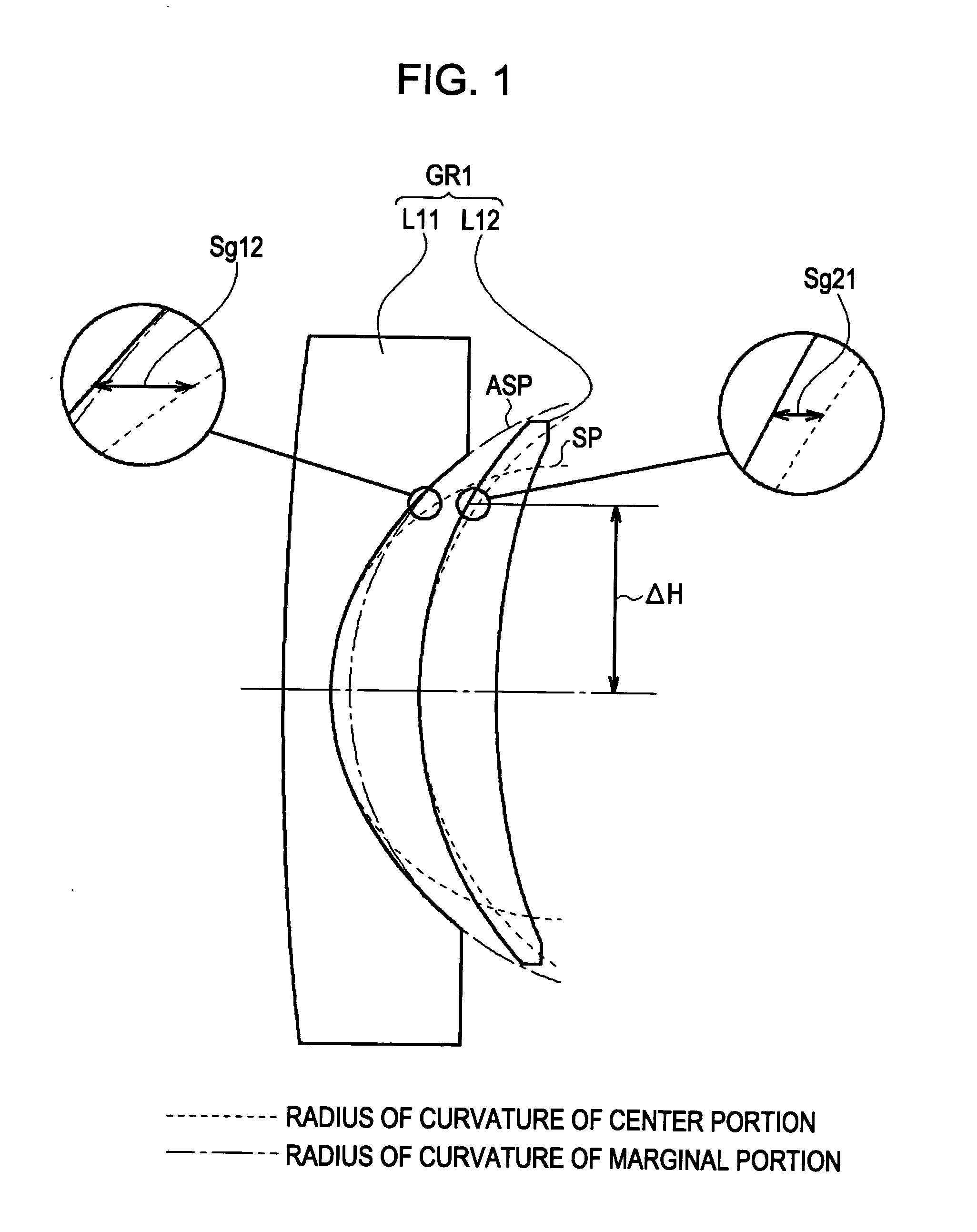
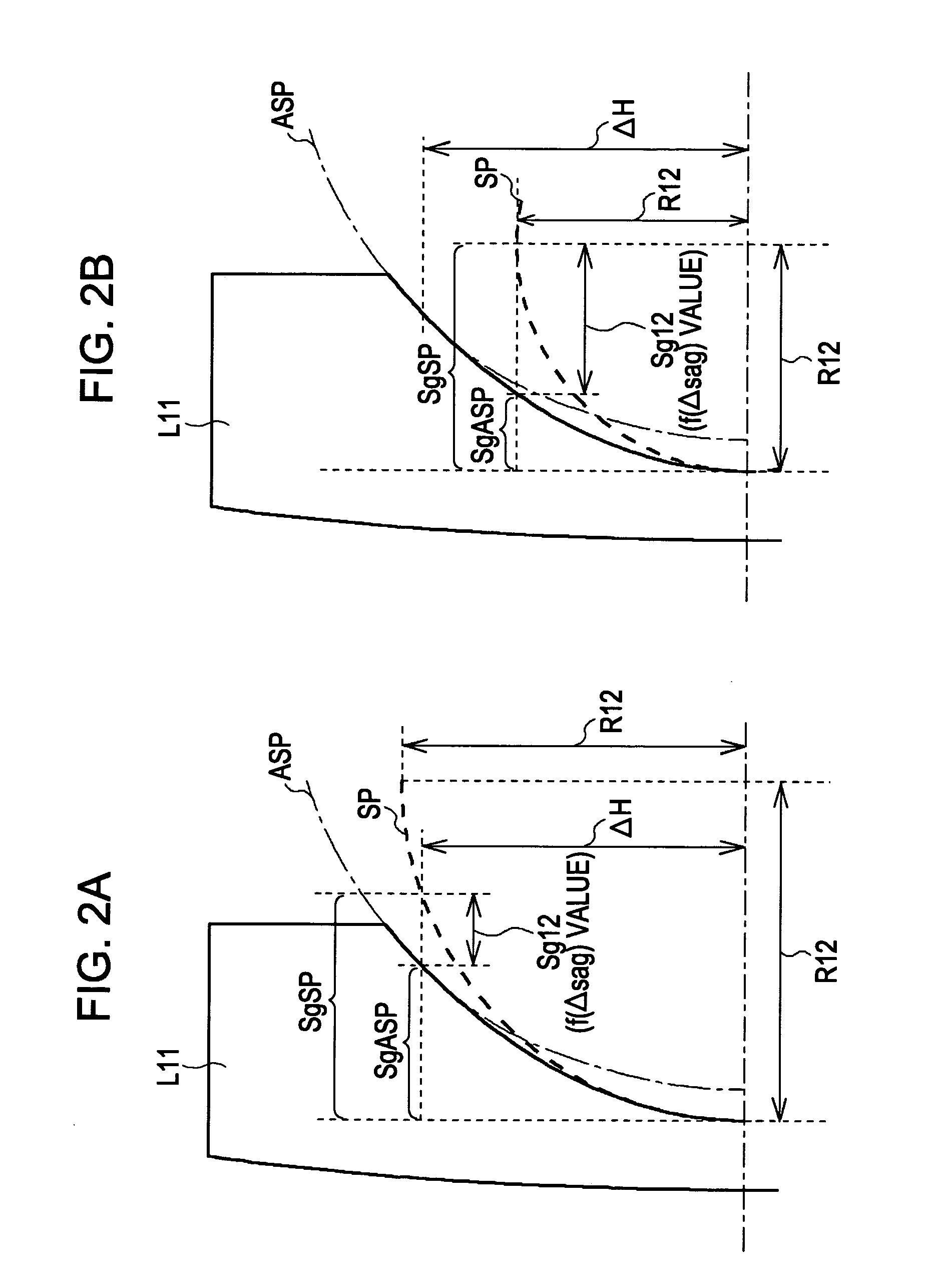
[0084]Specifically, in the zoom lens, during zooming from a wide-angle end to a telephoto end, the first lens group moves along a locus having a convex shape toward an image side while decreasing an air space between the first and second lens groups, and the second and third lens groups move toward the object side while increasing an air space therebetween. A surface closest to the object side in the second lens group is convex toward the object side and is aspheric, and the second lens group includes a cemented lens formed of a negative meniscus lens convex toward the object side and a positive lens.

[0085]Here, the lens surface closest to t...


PUM


Abstract

An image capture apparatus includes: a zoom lens; and an image pickup device converting an optical image formed by the zoom lens into an electric signal. The zoom lens includes, in order from the object side, a first lens group with a negative focal length, a second lens group with a positive focal length, a third lens group with a negative focal length, and a fourth lens group with a positive focal length. During zooming from a wide-angle end to a telephoto end, the first lens group moves along a locus having a convex shape toward an image side while decreasing an air space between the first and second lens groups, and the second and third lens groups move toward the object side while increasing an air space therebetween.

Description

BACKGROUND OF THE INVENTION[0001]1. Technical Field[0002]The present invention relates to a zoom lens and an image capture apparatus. In particular, the invention relates to, for example, a zoom lens, which is suitable for a digital still camera, a digital video camera, a surveillance camera, or the like while having a high zoom magnification power and being able to achieve an increase in imaging field angle sufficiently, and an image capture apparatus using the zoom lens.[0003]2. Description of the Related Art[0004]Recently, as the digital still camera market has become very large, users have varied demands for digital still cameras. To say nothing of an increase in image quality, a decrease in size, and a decrease in thickness, demand for an increase in the magnification of the image taking lens and an increase in the angle of view has also become very strong.[0005]Generally, there is a negative lead type zoom lens of which a lens group closest to the object side has a negative re...

Claims


Application Information

Patent Timeline
IPC IPC(8): G02B15/14
CPCG02B15/177G02B27/646G02B15/144511
Inventor YAMANO, HIROKI
Owner SONY CORP
Why Eureka
Try Eureka