
Routing frames in a computer network using bridge identifiers

a computer network and bridge technology, applied in the field of computer network routing frames, can solve the problems of limited number of customer networks that provider bridge networks can serve effectively and efficiently, 4096 identifiers available to specify different vlans, scaling problems,

Active Publication Date: 2010-07-01
JUMIPER NETWORKS INC
View PDF20 Cites 151 Cited by
  • Summary
  • Abstract
  • Description
  • Claims
  • Application Information

AI Technical Summary

Problems solved by technology

Bridges in VLAN topologies enforce the integrity of VLAN broadcast domains because such bridges are not permitted to bridge network traffic between VLANs.
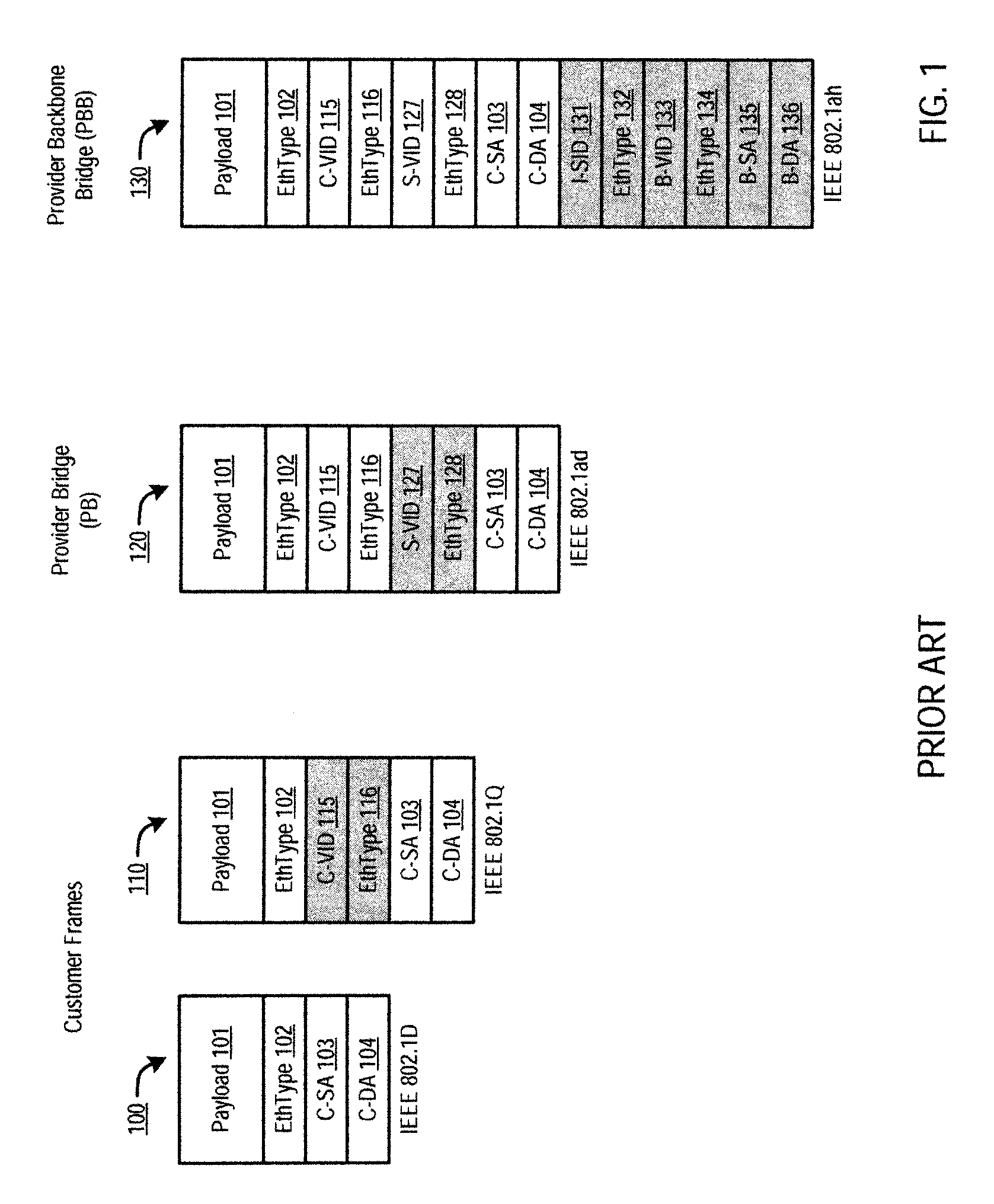
The drawback, however, is that under the IEEE 802.1Q specification, there are only 4096 identifiers available to specify different VLANs.
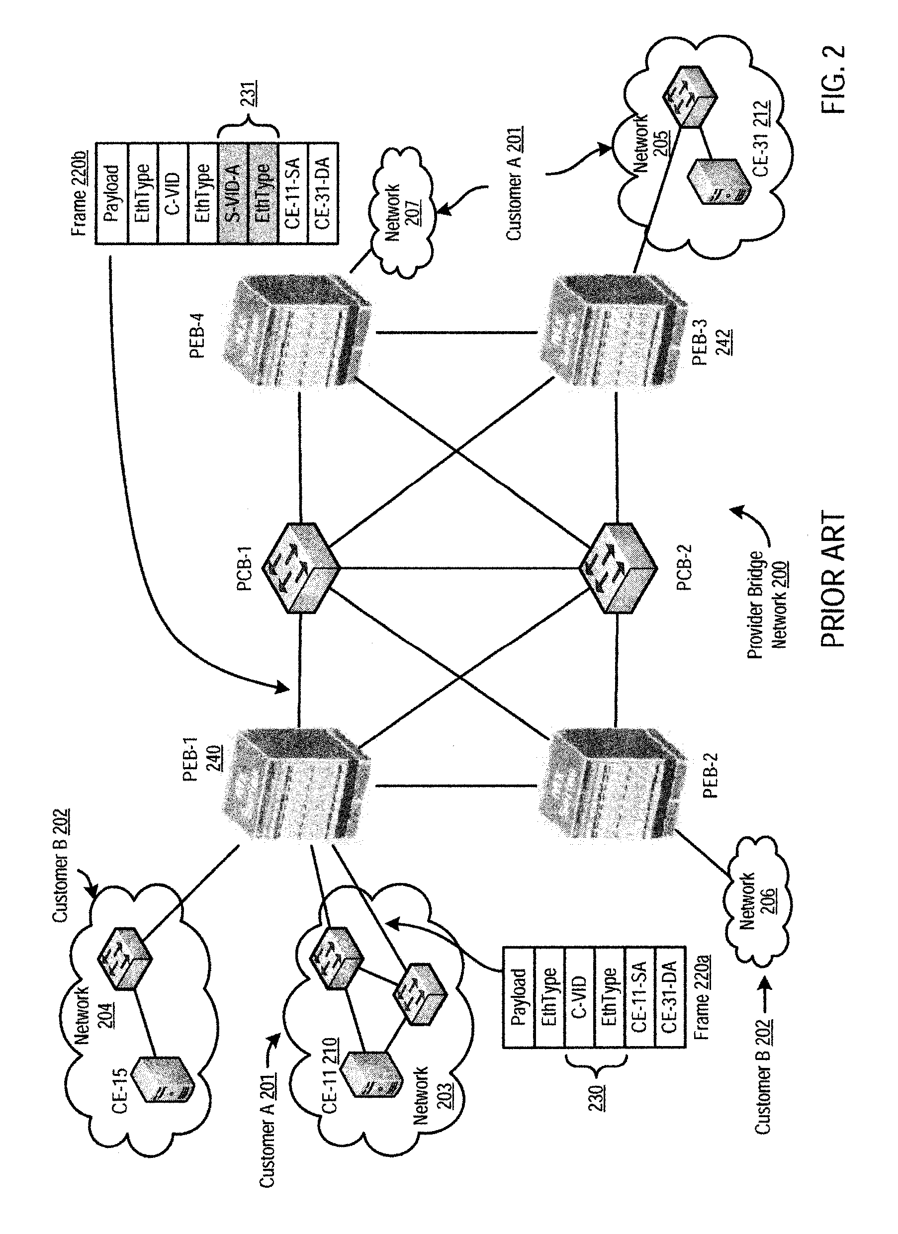
Even with the stacked VLAN protocols, provider bridge networks have scaling problems.
Because only 4,096 service VLAN identifiers are available under current protocols, provider bridge networks are limited in the number of customer networks they can serve effectively and efficiently.
Further, because provider bridges learn the MAC addresses for all customer devices, scaling issues often arise when a provider serves one or more customers with large virtual networks.
Bridge loops must be avoided because such loops result in traffic that floods the network.
There are certain disadvantages to the spanning tree protocol used in the networks described above with reference to FIGS. 1-4.
Because the spanning tree protocol disables links that are not part of the forwarding tree, bottlenecks are often created by concentrating traffic onto selected links.
Unfortunately, current generation hardware for typical rack-mounted bridges that form the edge of these networks do not support MAC-in-MAC encapsulation, thereby limiting the use of TRILL, SPPBB, and similar solutions that provide shortest path routing at Layer-2 level.

Method used


Image

  • Routing frames in a computer network using bridge identifiers
  • Routing frames in a computer network using bridge identifiers
  • Routing frames in a computer network using bridge identifiers

Examples


Embodiment Construction

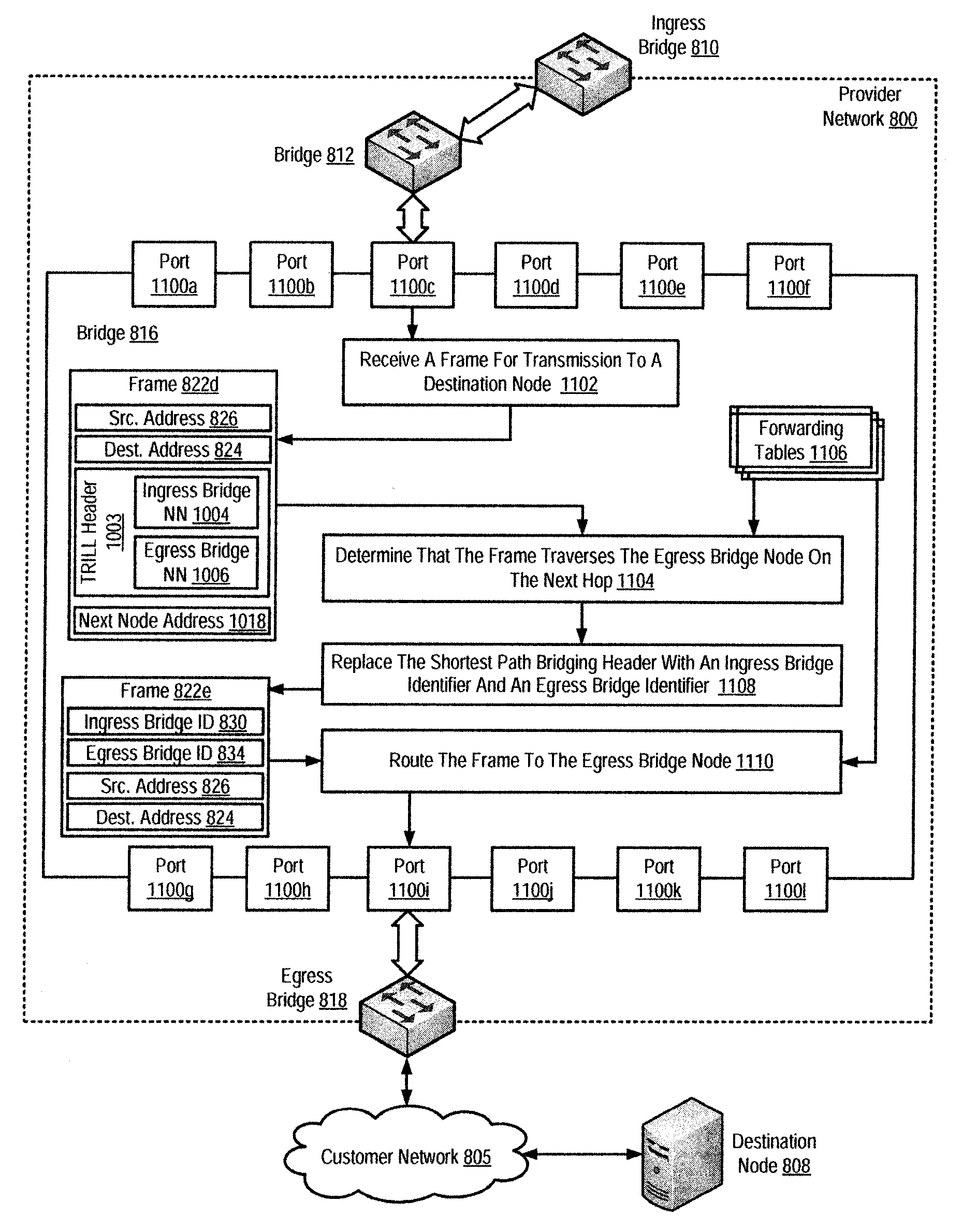
[0055]While certain exemplary embodiments are described in detail and shown in the accompanying drawings, it is to be understood that such embodiments are merely illustrative of and not devised without departing from the basic scope thereof, which is determined by the claims that follow.

[0056]Although the following disclosure is discussed using terminology related to Ethernet links, various IEEE 802 standards and TRILL, these are merely by way of example and illustration, and the scope of the present invention is not so limited, but extends to the fullest scope defined by the claims herein.

[0057]Typical edge bridges used in conjunction with rack-mounted equipment do not support the MAC-in-MAC encapsulation required in current shortest path provider backbone bridging network solutions, such as for example TRILL network solutions. When modified for routing frames in a computer network using bridge identifiers according to embodiments of the present invention, however, such bridges can...


PUM


Abstract

Methods, apparatus, and products for routing frames in a network using bridge identifiers, wherein the network includes a plurality of bridge nodes. At least one of the bridge nodes operates as an ingress bridge node through which frames are received into the network. At least one of the bridge nodes operates as an egress bridge node through which frames are transmitted out of the network. One of the bridge nodes receives, from the ingress bridge node, a frame for transmission to a destination node. The destination node connects to the network through the egress bridge node. The frame includes an ingress bridge identifier and an egress bridge identifier. The bridge that received the frame then routes the frame to the egress bridge node through which the destination node connects to the network in dependence upon the ingress bridge identifier and the egress bridge identifier included in the frame.

Description

CROSS-REFERENCE TO RELATED APPLICATION[0001]Not applicable.TECHNICAL FIELD[0002]The present invention relates to the field of computer networking, and in particular to a technique for routing frames in a computer network using bridge identifiers.BACKGROUND OF THE INVENTION[0003]Early computer networks consisted of a small number of devices attached together using a single cable. Computer networks have since evolved, however, beyond a simple collection of attached devices. Current computer networks may connect thousands of devices spread across large local areas, and these local area networks may in turn be connected together to form still larger networks such as, for example, the Internet.[0004]Today's computer networks often interconnect widely-disparate devices distributed throughout multiple local networks into a single virtual network. Virtual networking technology allows devices located on a single physical network to operate as part of multiple virtual networks. Such virtual n...

Claims


Application Information

Patent Timeline
Patent Type & Authority Applications(United States)
IPC IPC(8): H04L12/28
CPCH04L12/462H04L45/04H04L45/12H04L45/66
Inventor MEHTA, APURVARAMANATHAN, RAMASAMYMEHTA, KUMARRAMAKRISHNAN, RAMANARAYANAN
Owner JUMIPER NETWORKS INC
Learn More