
Variable rate transport fees based on vehicle exhaust emissions

a technology of vehicle exhaust and transportation fees, applied in the field of transportation and allocation of vehicle user costs, can solve the problems of increasing the number of vehicles on the road, traffic congestion and pollution from exhaust emissions, and many municipalities have difficulty balancing the requirements and desires of commuters, and achieves higher monetary or non-monetary demands

Inactive Publication Date: 2010-06-24
IBM CORP
View PDF17 Cites 29 Cited by
  • Summary
  • Abstract
  • Description
  • Claims
  • Application Information

AI Technical Summary

Benefits of technology

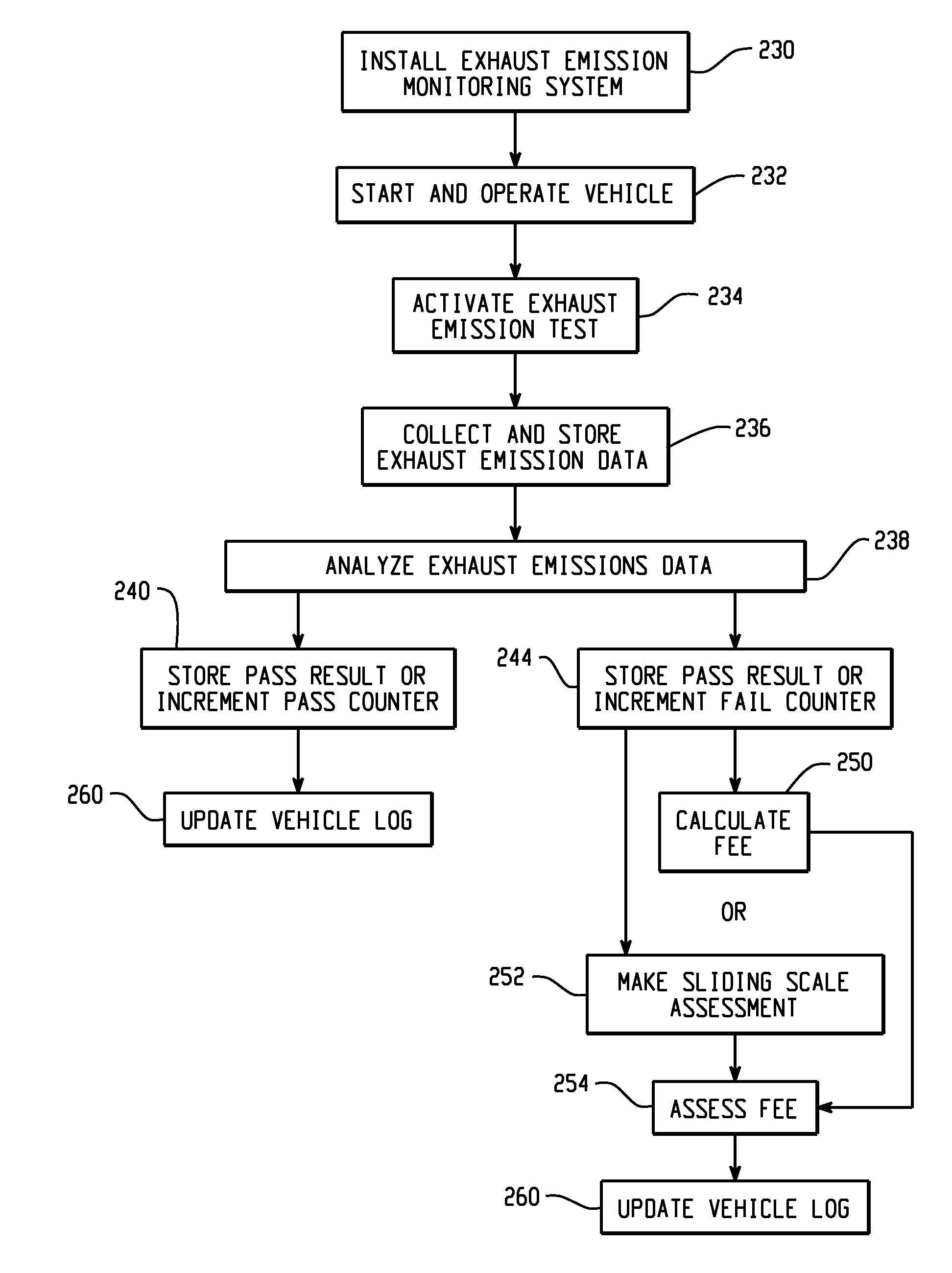
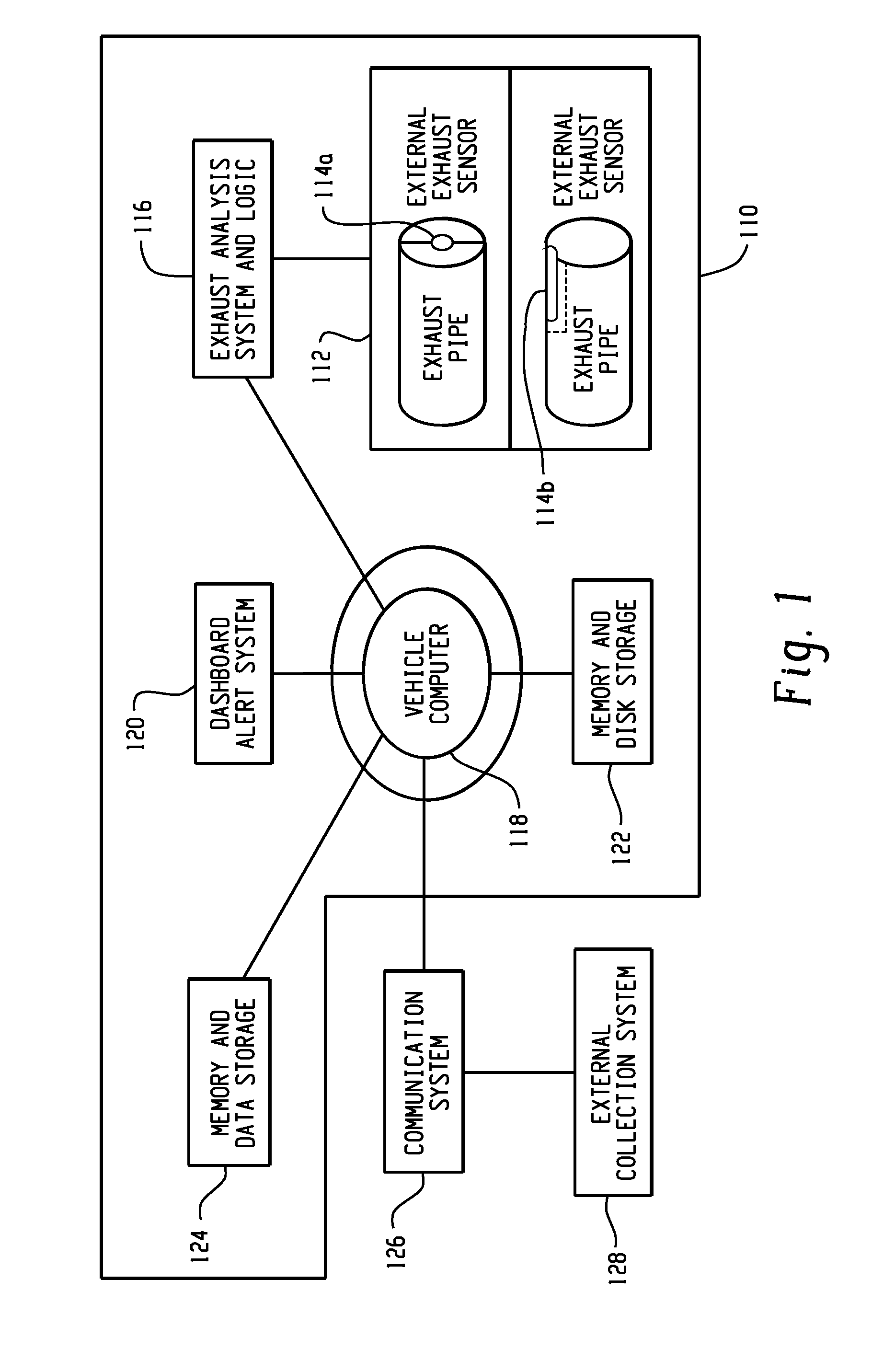
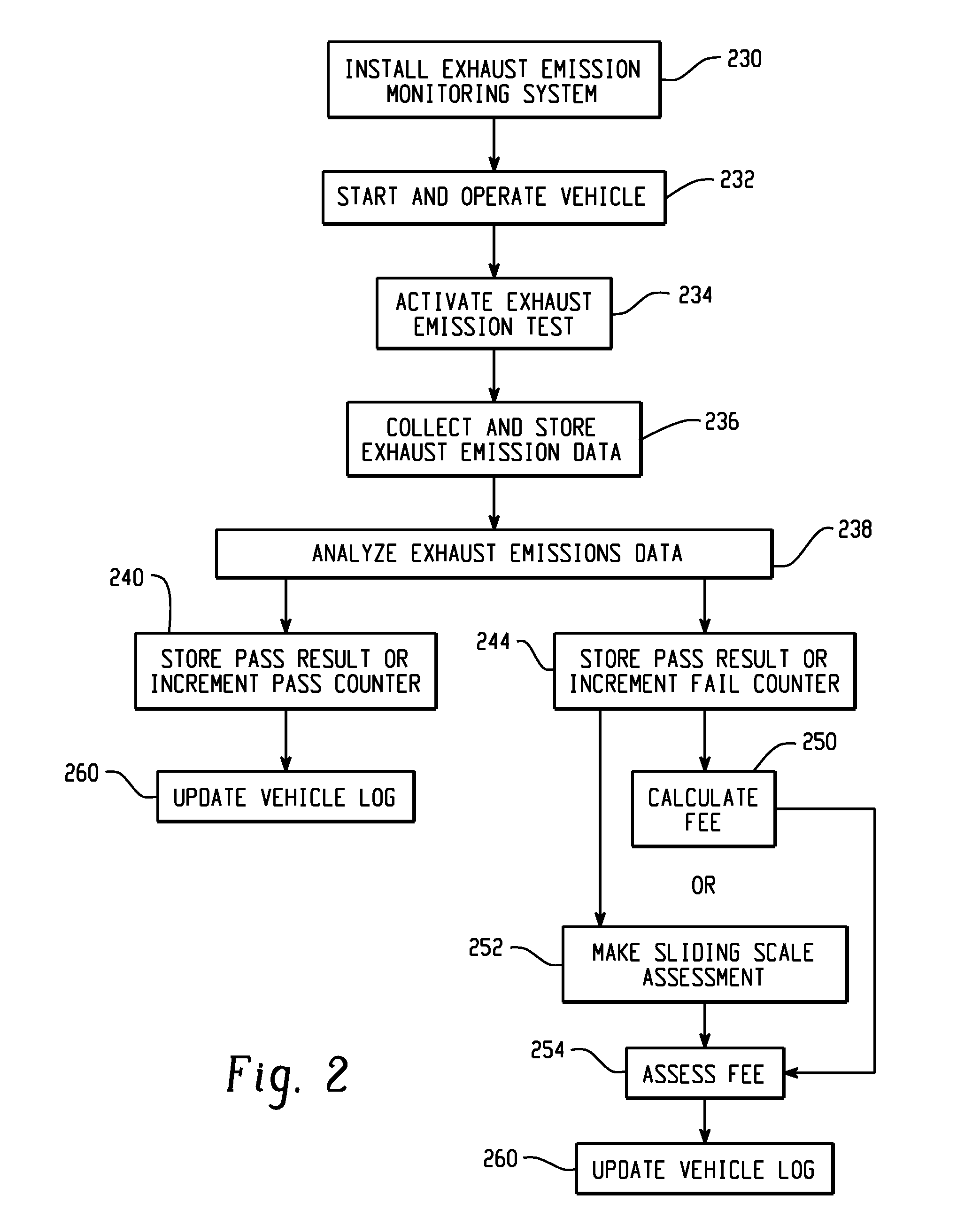
[0004]The present invention introduces real-time vehicle exhaust emissions testing and reporting system that monitors individual vehicles for pollutants in the exhaust. If excess pollutants are detected, operational charges such as toll charges and parking fees, along with governmental license renewals and the like are increased for offending vehicles. This invention provides an incentive to commuters to maintain well running vehicles, while imposing higher monetary or non-monetary demands on those commuters who pollute the air with improperly maintained and / or inefficient vehicles.

Problems solved by technology

The number of vehicles on the roads continues to grow exponentially, where in some areas, traffic congestion and pollution from exhaust emissions has become very problematic.
An important issue when considering transit issues is the impact of each existing, planned, and proposed transit system on the environment.
In viewing these transit requirements as a whole, many municipalities have difficulty balancing the requirements and desires of commuters against such things as traffic congestion, environmental impact, availability and use of mass transit, and equitable distribution of transit costs.

Method used


Image

  • Variable rate transport fees based on vehicle exhaust emissions
  • Variable rate transport fees based on vehicle exhaust emissions
  • Variable rate transport fees based on vehicle exhaust emissions

Examples


Embodiment Construction

[0013]For convenience purposes, the Detailed Description of the Invention has the following sections.

I. General Description

[0014]This invention introduces an active vehicle exhaust monitoring system, whereby at any given point in time, vehicle exhaust can be analyzed for pollutants in excess of permissible levels. The term “vehicle” encompasses automobiles as well as buses, boats, trains, lorries and any apparatus configured to carry occupants and passengers along dedicated thoroughfare infrastructures (e.g. highways or railroad tracks), and which also may define a thoroughfare through their regular paths and schedules (e.g. a shipping channel or inter-coastal waterway). In one embodiment, such an exhaust analyzer element would be installed in a vehicle as a standard integral component during factory assembly. However, it also may include an after-market device. Most modern land vehicles are equipped with a relatively sophisticated computer system. The exhaust analysis and reporting...


PUM


Abstract

This invention provides a system and method of detecting and responding to individual vehicle exhaust emissions such that a vehicle producing exhaust emissions containing pollutants in excess of required standards is assessed a higher toll or other fees than non-offending vehicles. Upon correction of the problem when emissions are determined to be within acceptable ranges, the fees are re-adjusted. Vehicle fees can be assessed on a sliding scale regardless of “acceptable thresholds” whereupon a higher levels of pollution emitted by the vehicle require payment of a higher fee than that paid by a vehicle with a lower level. Sensors may be installed within individual vehicles, or may be externally mounted to detect emissions. The use of a computer program and program code may be used for collecting and quantifying the level of pollution in the emissions and for assessing a suitable fee based on the level.

Description

FIELD OF THE INVENTION[0001]The following invention relates generally to the field of transportation and allocation of vehicle user costs based upon contribution of harmful emissions by a motor vehicle to the environment.BACKGROUND OF THE INVENTION[0002]The automobile is by far the most common and generally desired form of daily transportation for commuters of all kinds. The number of vehicles on the roads continues to grow exponentially, where in some areas, traffic congestion and pollution from exhaust emissions has become very problematic. These vehicles include cars, vans, trucks, buses, SUVs and other ground vehicles that utilize gasoline or diesel-powered engines for propulsion. Travelers have many differing transit requirements, options, and habits. Management of transit thoroughfares include public roads, regional and intrastate highways, interstate highways, public toll and access roads, private toll and access roads, and all forms of public / mass transportation. An importan...

Claims


Application Information

Patent Timeline
IPC IPC(8): G07B15/02G01N7/00G06Q50/00G06Q30/00G06Q20/00G07B15/06
CPCG06Q30/02G06Q30/0283G07C5/085G07C5/008G06Q50/30G06Q50/40
Inventor ASHBY, DUNCANHAMILTON, II, RICK A.LAMBA, NAVEENLIM, COLIN FUNG WANMORRIS, BENJAMIN G.SEAMAN, JAMES W.
Owner IBM CORP
Learn More