
Head-mounted type image display device

a display device and head-mounted technology, applied in the direction of instruments, cathode-ray tube indicators, spectacles/goggles, etc., can solve the problems of poor visibility of the display screen, the device can display only relatively little information, and the conventional head-mounted type image display device may not well satisfy the need to see a lot of information, etc., to achieve good viewability and not impair the mobility of the device

Active Publication Date: 2010-06-24
OLYMPUS CORP
View PDF3 Cites 26 Cited by
  • Summary
  • Abstract
  • Description
  • Claims
  • Application Information

AI Technical Summary

Benefits of technology

[0012]An object of the invention contrived in view of the problems described above is to provide a novel head-mounted type image display device which can display a lot of information by a multi-screen with good viewability, without impairing mobility of the device.
[0025]In the present invention, the head-mounting unit in a state where the unit is attached to the head of the observer supports the plurality of eyepiece optical units such that an emitting optical axis of each eyepiece optical unit substantially passes through the eyeball rolling center of the corresponding eyeball and, when the emitting optical axis of one eyepiece optical unit passes through a pupil of the corresponding eyeball thereof as a result of rolling of the eyes, the emitting optical axis of another eyepiece optical unit does not pass through a pupil of the corresponding eyeball thereof. Accordingly, a lot of information can be displayed by a multi-screen with good viewability without impairing the mobility of the device, by displaying display screens of a plurality of eyepiece optical units as multi-screens separated from each other in a field of view and switching information to be observed by moving his eyes from one screen to another to see information.

Problems solved by technology

Besides, since the head-mounted type image display device has a relatively small display screen to allow mobile use thereof, the device can display only relatively little information.
Therefore, the conventional head-mounted type image display device may not well satisfy a need to see a lot of information at the same time as in an information display.
However, simply providing a plurality of eyepiece optical units to display information by a multi-screen results in poor visibility of a display screen and deterioration of mobile-maneuverability due to juxtaposed or overlapped display images, different images being simultaneously observed by left and right eyes, respectively, and unnecessary image light being incident on the eyes, which are caused by the plurality of eyepiece optical units.

Method used


Image

  • Head-mounted type image display device
  • Head-mounted type image display device
  • Head-mounted type image display device

Examples


first embodiment

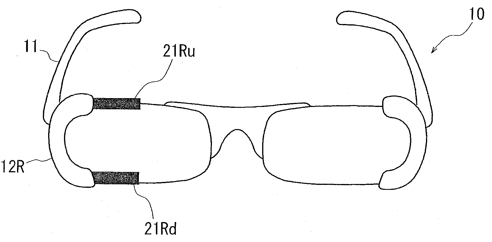
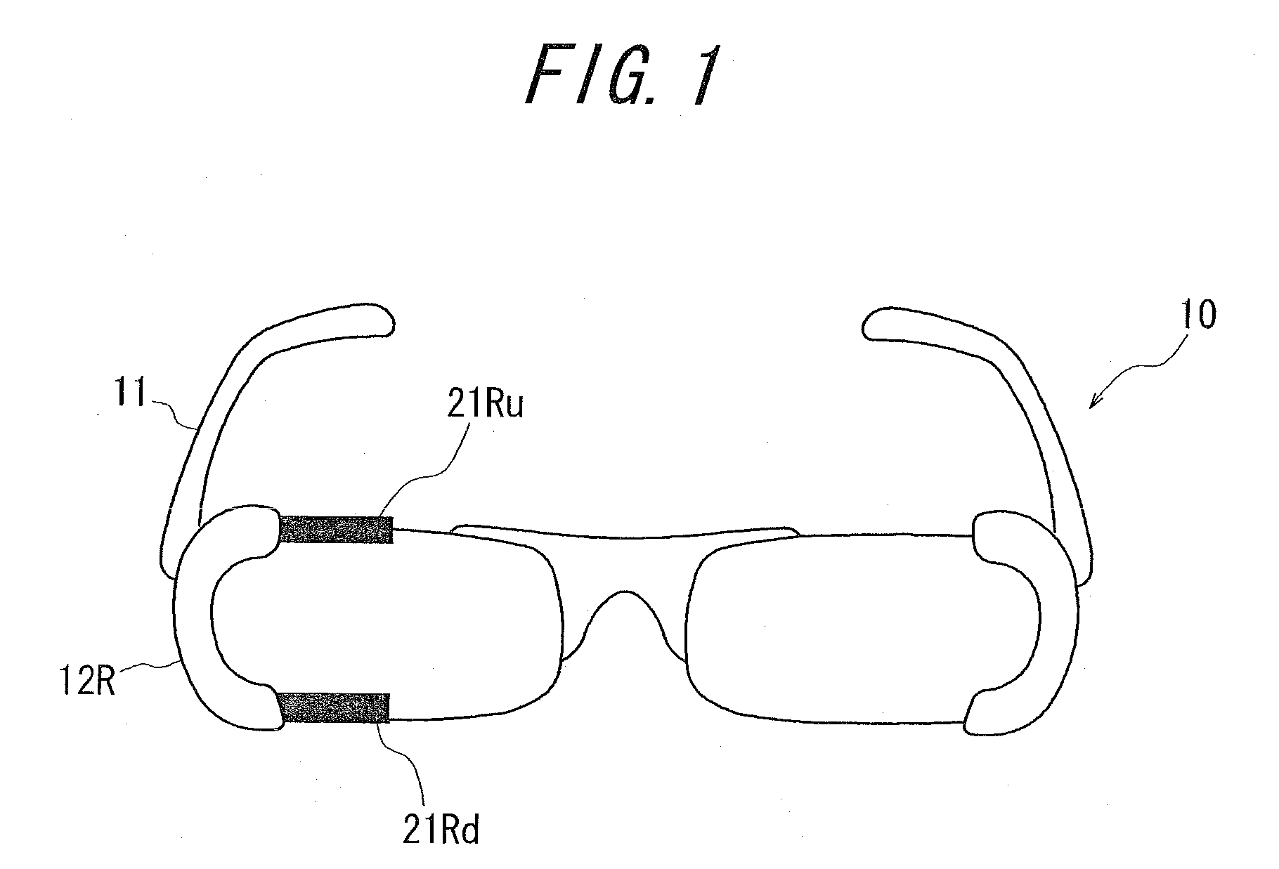
[0044]FIG. 1 is a perspective view showing a schematic structure of a head-mounted type image display device according to the first embodiment of the present invention. The head-mounted type image display device 10 is of an eyeglass integrated type adapted for right eye use and includes, in a state the observer has worn a eyeglass frame 11 as a head-mounting unit, an upper bar-like light guiding unit 21Ru held at the upper part of a right eye rim 12R of the eyeglass frame 11 to extend within the filed of view of the right eye and a lower bar-like light guiding unit 21Rd held at the lower part of the right eye rim 12R to extend within the field of view of the right eye.

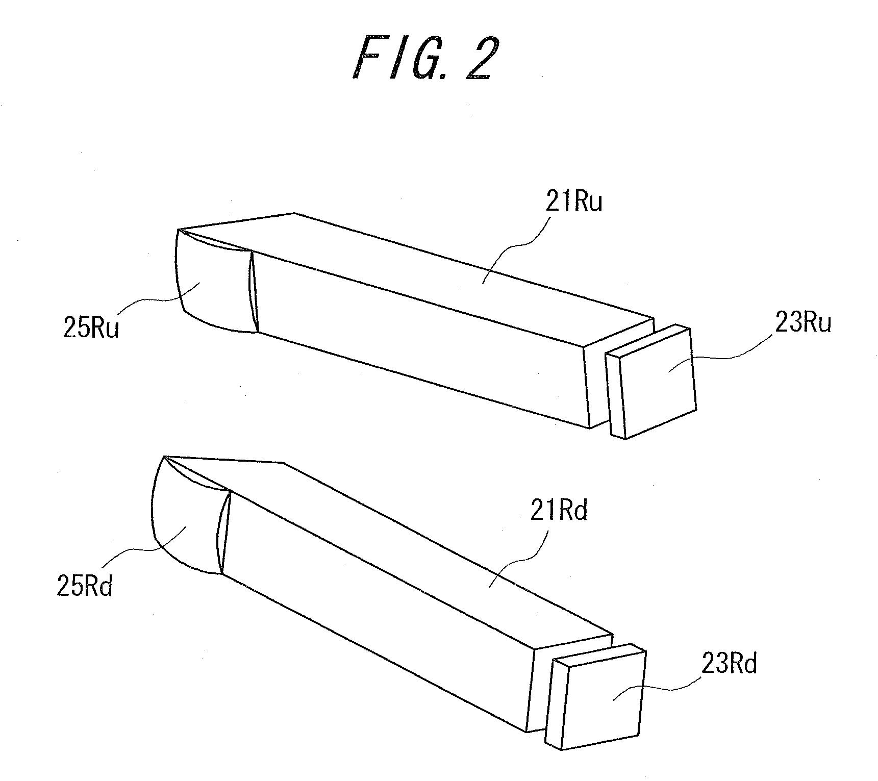
[0045]The upper bar-like light guiding unit 21Ru is formed to have, for example, a rectangular cross section as shown in a schematic perspective view of FIG. 2, and holds an incident end face on one end thereof at the upper part of the right eye rim 12 such that the end face faces a displaying element 23Ru consisting o...

second embodiment

[0055]FIG. 6 is a perspective view showing a schematic structure of a head-mounted type image display device according to a second embodiment of the present invention. This head-mounted type image display device 30 is of eyeglass integrated type and includes, in a state where the observer wears a eyeglass frame 31 as a head-mounting unit, a lower bar-like light guiding unit 41Ld for left eye held at the lower part of a left eye rim 32L of the eyeglass frame 31 to extend within the filed of view of the left eye and a lower bar-like light guiding unit 41Rd held at the lower part of the right eye rim 32R of the eyeglass frame 31 to extend within the field of view of the right eye.

[0056]The lower bar-like light guiding unit for left eye 41Ld and the lower bar-like light guiding unit for right eye 41Rd each guide image light of an image displayed on the displaying element from the incident end face to the other end thereof and respectively emit the light via a lower eyepiece optical unit...

third embodiment

[0065]FIG. 10 is a perspective view showing a schematic structure of a head-mounted type image display device according to a third embodiment of the present invention. This head-mounted type image display device 50 is different from the head-mounted type image display device 30 of the second embodiment, in that the former is further provided with a upper bar-like light guiding unit for left eye 41Lu extending within the field of view of the left eye and a upper bar-like light guiding unit for right eye 41Ru extending within the field of view of the right eye retained at the upper portions of left eye rim 32L and the right eye rim 32R of the eyeglass frame 31, respectively, such that these four bar-like light guiding units are positioned apart from each other in both the horizontal and vertical directions.

[0066]The upper bar-like light guiding unit for left eye 41Lu and the upper bar-like light guiding unit for right eye 41Ru each guide image light of an image displayed on the displa...


PUM


Abstract

The present invention provides a novel head-mounted type image display device capable of displaying a lot of information with good viewability by multi-screens without impairing mobility of the device. The device comprises a plurality of eyepiece optical units 25Ru, 25Rd emitting image light to be displayed toward corresponding eye balls respectively and a head-mounting unit 11 for supporting the plurality of eyepiece optical units 25Ru, 25Rd and adapted to detachably attached to the head of an observer. The head-mounting unit 11 in a state where the unit is attached to the head of the observer supports the plurality of eyepiece optical units 25Ru, 25Rd such that an emitting optical axis of each eyepiece optical unit 25Ru, 25Rd substantially passes through the eyeball rolling center of the corresponding eyeball and, when the emitting optical axis of one eyepiece optical unit passes through a pupil of the corresponding eyeball thereof as a result of rolling of the eyes, the emitting optical axis of another eyepiece optical unit does not pass through a pupil of the corresponding eyeball thereof.

Description

CROSS-REFERENCE TO APPLICATIONS[0001]The present application claims the priorities of Japanese Patent Application No. 2008-322524 filed on Dec. 18, 2008, which are herein incorporated in their entirety for reference.FIELD OF THE INVENTION[0002]The present invention relates to a head-mounted type image display device, particularly, to a novel head-mounted type image display device capable of displaying a multi screen.BACKGROUND OF THE INVENTION[0003]As a conventional head-mounted type image display device, devices capable of mobile use such as head-set type devices and eyeglass type devices, for example, have been suggested (e.g. JP2003-502713A and JP2006-003879A).[0004]FIG. 16 is a view showing a schematic structure of a conventionally proposed head-mounted type image display device, wherein FIG. 16(a) is a front view, FIG. 16(b) is a side view, and FIG. 16(c) is a plan view. This head-mounted type image display device 100 is of the type for left eye and has a head-set type head sup...

Claims


Application Information

Patent Timeline
Patent Type & Authority Applications(United States)
IPC IPC(8): G02B27/01G02C11/00
CPCG02B2027/0123G02B27/0172
Inventor SUGIHARA, RYOHEITATSUTA, SEIJIIBA, YOICHI
Owner OLYMPUS CORP
Learn More