
Passive distance estimation for imaging algorithms

a technology of passing distance estimation and imaging algorithms, applied in the field of cameras or electronic devices, can solve the problems of difficult tracking, complicated user experience, and time-consuming operation of af operations

Inactive Publication Date: 2010-06-24
NOKIA CORP
View PDF7 Cites 33 Cited by
  • Summary
  • Abstract
  • Description
  • Claims
  • Application Information

AI Technical Summary

Benefits of technology

[0018]Still further according to the third aspect of the invention, the apparatus may further comprise: a memory, configured to store all or selected dimensions of the one or more known dimensions.
[0019]According yet further to the third aspect of the invention, the apparatus may further comprise: an autofocus module, configured to focus a lens system of the camera to the distance and further configured to move the lens system to a best focusing position by carrying out an autofocus refinement search around the distance for implementing a fine automatic autofocusing procedure which is one of the one or more imaging algorithms.
[0020]According further still to the third aspect of the invention, apparatus may further comprise: a flash determining module, configured to adjust flash parameters of the camera which is one of the one or more imaging algorithms.
[0021]Yet still further according to the third aspect of the invention, the object selecting module may be configured to identify, using object recognition, a plurality of objects from ...

Problems solved by technology

This AF operation is usually time consuming which complicates a user experience while operating the camera.
The initial search may be similar to the one-time autofocus procedure outline above, but the tracking may be quite difficult due to the movement of the object.
Usually these methods are rather complex, time consuming and require substantial amount of computation power.
Also existing art utilizing distance estimation has not been applied to improving AF, flash photography and user experience for image capturing.
In existing implementations the distance to the subject may be estimated using a lens position such that the error in the lens position estimates may be as much as 50%, because of mechanical tolerances and lack of lens position measurement sensors.
The errors will be cumulative and will be reflected in the error of the power level for, e.g., flash assisted photography.

Method used


Image

  • Passive distance estimation for imaging algorithms
  • Passive distance estimation for imaging algorithms
  • Passive distance estimation for imaging algorithms

Examples


Embodiment Construction

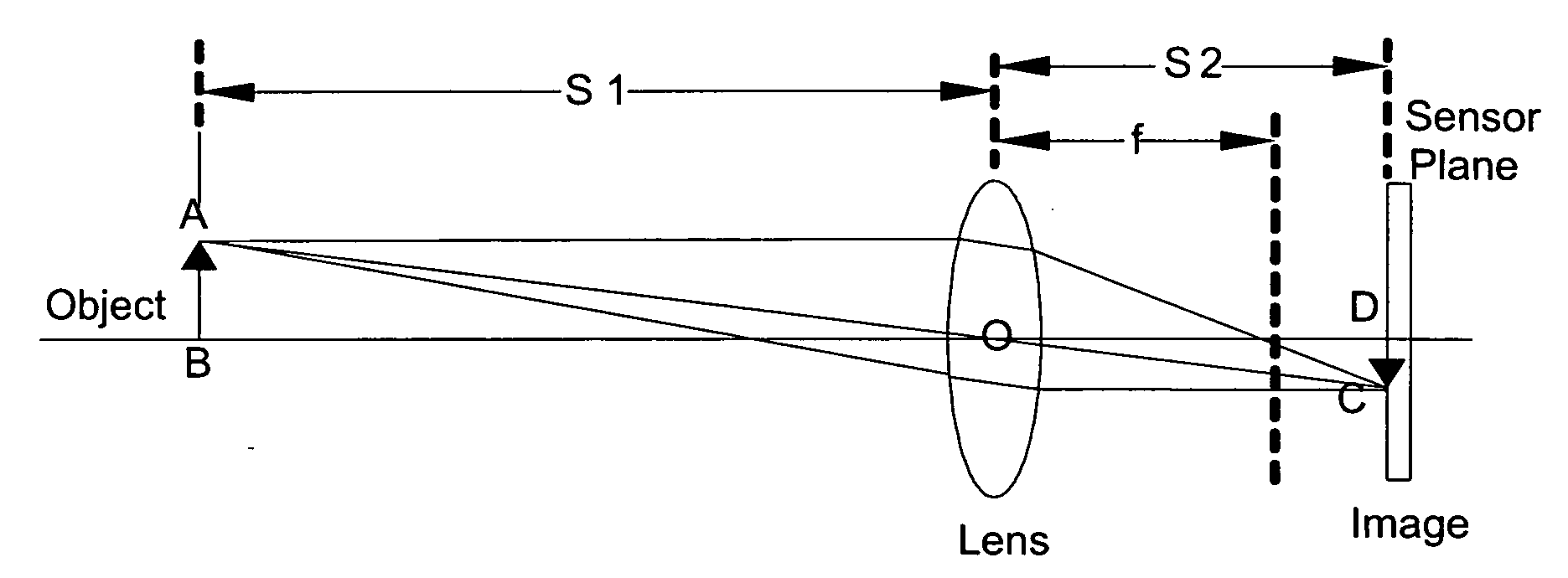
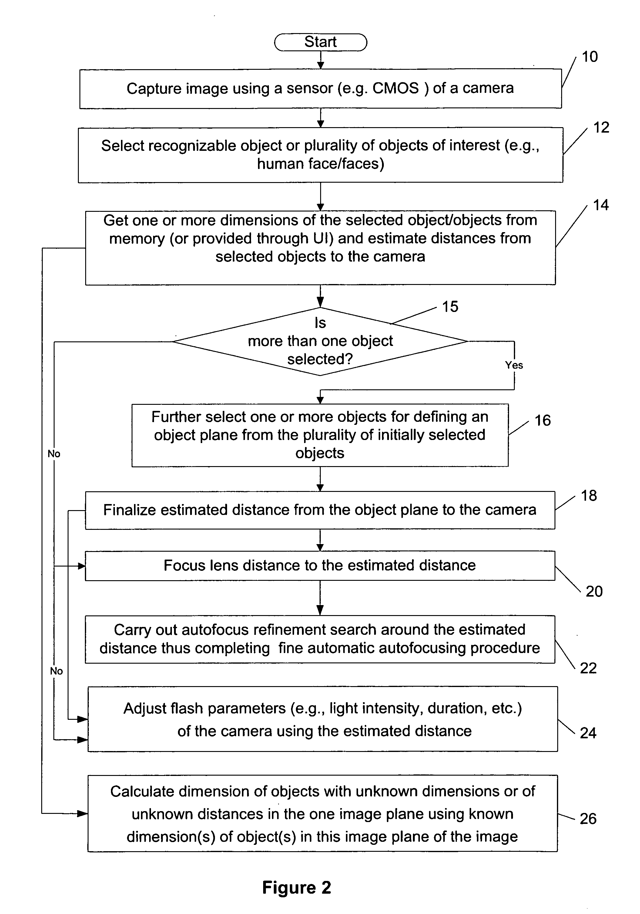
[0030]A new method, apparatus and software product are presented for a passive estimation of a distance between a camera or an electronic device comprising the camera (e.g., a wireless camera phone) and an identified object or objects (e.g., automatically recognizable by the camera) having one or more known dimensions and located substantially in one object plane using an image (e.g., provided by the camera) for implementing by the camera / electronic device one or more imaging algorithms (e.g., autofocusing, flash adjustment, etc.) using that distance.

[0031]With the introduction of object (e.g., human face) recognition and tracking algorithms in most camera systems, additional parameters such as feature size (e.g., human face size, distance between eyes, nose to eyes ratio, nose to mouth ratio and other possible face characteristics) become readily available which may be used to improve existing auto-focus, flash control, image quality and user experience, according to various embodi...


PUM


Abstract

The specification and drawings present a new method, apparatus and software product for a passive estimation of a distance between a camera or an electronic device comprising the camera (e.g., a wireless camera phone) and an identified object or objects (e.g., automatically recognizable by the camera) having one or more known dimensions and located substantially in one object plane using an image (e.g., provided by the camera) for implementing by the camera / electronic device one or more imaging algorithms (e.g., autofocusing, flash adjustment, etc.) using that distance.

Description

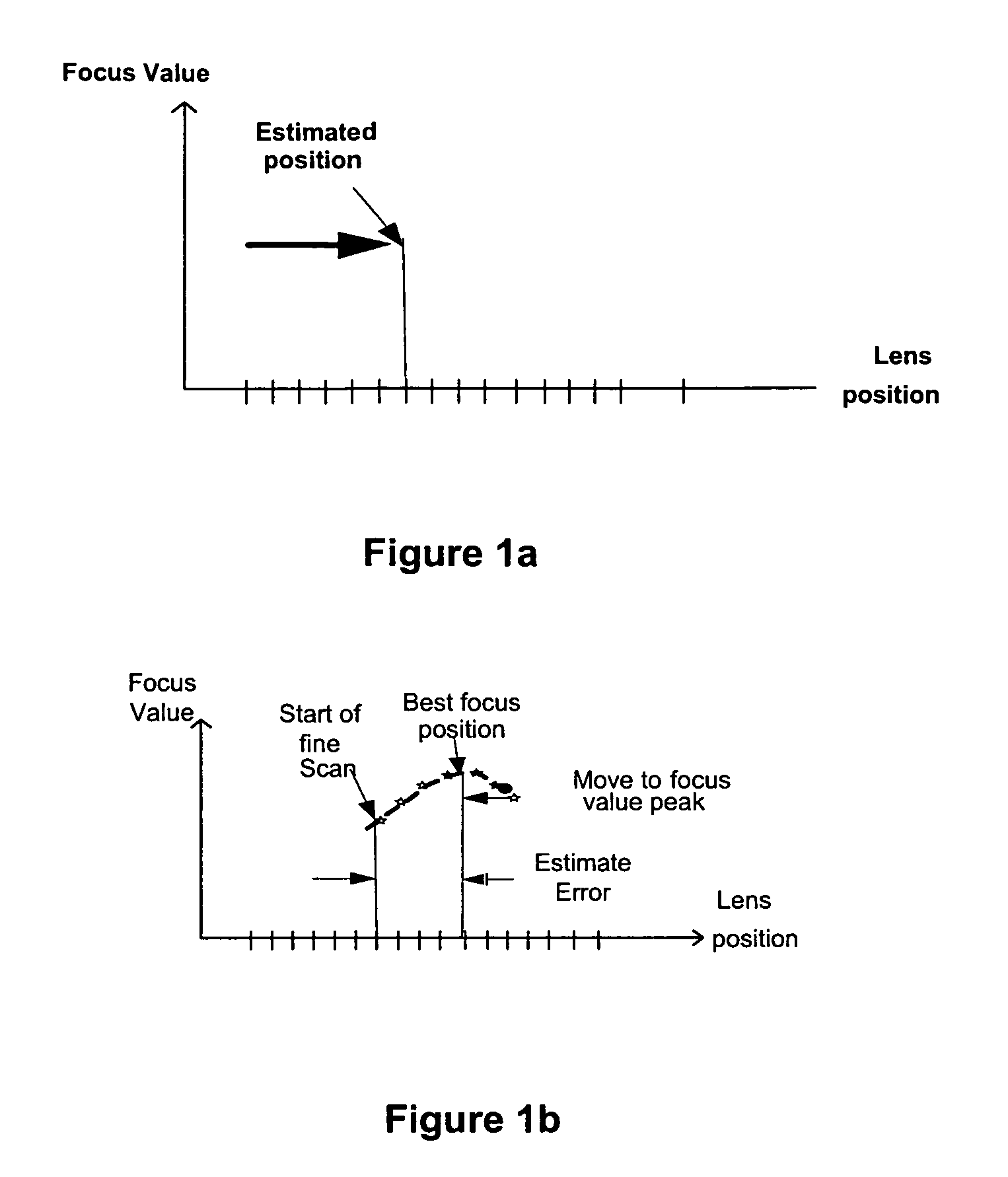
TECHNICAL FIELD[0001]The present invention relates generally to cameras or electronic devices comprising cameras and, more specifically, to passive estimation of distance between the camera and identified object / objects and implementing imaging algorithms (e.g., autofocusing, flash adjustment, etc.) using the estimated distance.BACKGROUND ART[0002]In passive autofocus (AU) systems, the focusing is usually carried out by analyzing the captured image and positioning the lens where the image is sharpest, in the smallest number of steps to minimize the time taken for focusing. Typically, one time autofocus (AF) in an AF system of cameras is accomplished by moving the focusing from infinity towards a macro side with larger steps (usually called rough steps) until the focus value which is a measure of sharpness starts to decrease, indicating, that the peak has been passed. The area around the peak is then re-scanned with reduced step size, so that the sharpness peak may be located more pr...

Claims


Application Information

Patent Timeline
IPC IPC(8): H04N5/232
CPCG02B7/36H04N5/2354H04N5/23212G03B13/36H04N23/74
Inventor DOSSAJI, TAIPETROVICH, DUANESAKIJARVI, JUHA
Owner NOKIA CORP
Learn More