
Aircraft Seat

Active Publication Date: 2010-06-24
KI HOLDINGS
View PDF11 Cites 15 Cited by
  • Summary
  • Abstract
  • Description
  • Claims
  • Application Information

AI Technical Summary

Benefits of technology

[0007]The present invention has been made in view of such problems with which the prior art has encountered, and one purpose of the present invention is to provide an aircraft seat which can receive the load of a sitting person with only the back plate member, using no seat back frame, thus eliminating the need for sacrificing the sitting space, resulting from the existence of the seat back frame, and at the same time, allowing the weight of the seat to be reduced.
[0025]In addition, by the nature of the composite material, such as a GFRP (Glass Fiber) / CFRP (Carbon Fiber) one, or the like, the surface of the back plate member is resinous, thus depending upon the way of surface treatment of a visible portion, such as the rear face, or the like, the need for covering with a surface cloth, a decorative panel, or the like, can be eliminated. Thereby, the number of parts can be reduced, and the need for installation working for a surface cloth, a decorative panel, or the like, can be eliminated.

Problems solved by technology

However, such a prior art has provided the strength required to withstand the load of the sitting person by increasing the width of the seat back frame, and making the portion bulging toward the side of the sitting person larger.
However, there has been a problem that, from the viewpoint of the good sitting feeling which is to be obtained from the seat back cushion itself, the thickness may be unnecessarily large, with the sitting space being sacrificed or the weight of the seat being increased by the amount corresponding to the unnecessary thickness.
In addition, from the viewpoint of esthetic appearance of the seat back, the visible surfaces are covered with a surface cloth or a separately attached decorative panel, thus there has been a problem that the number of parts is increased, resulting from the covering.
Further, loading and unloading of such a seat back cushion and a surface cloth require complex operations, thus there has been a problem that the loading and unloading can take a considerable amount of man-hours.

Method used


Image

  • Aircraft Seat
  • Aircraft Seat
  • Aircraft Seat

Examples


Embodiment Construction

[0035]Hereinbelow, a preferred embodiment of the present invention will be described with reference to the drawings. The respective drawings from FIG. 1 to FIG. 9(B) illustrates one embodiment of the present invention.

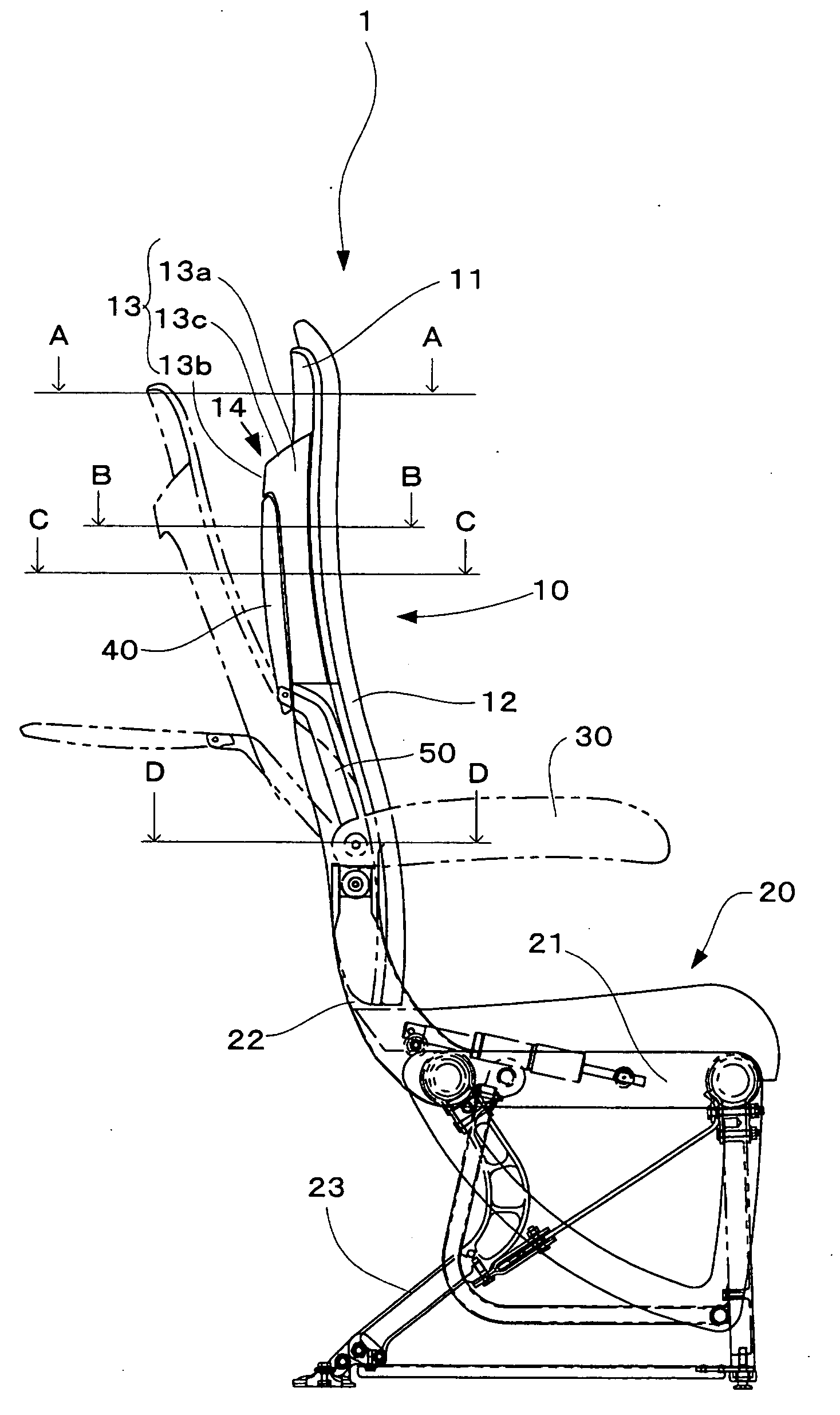
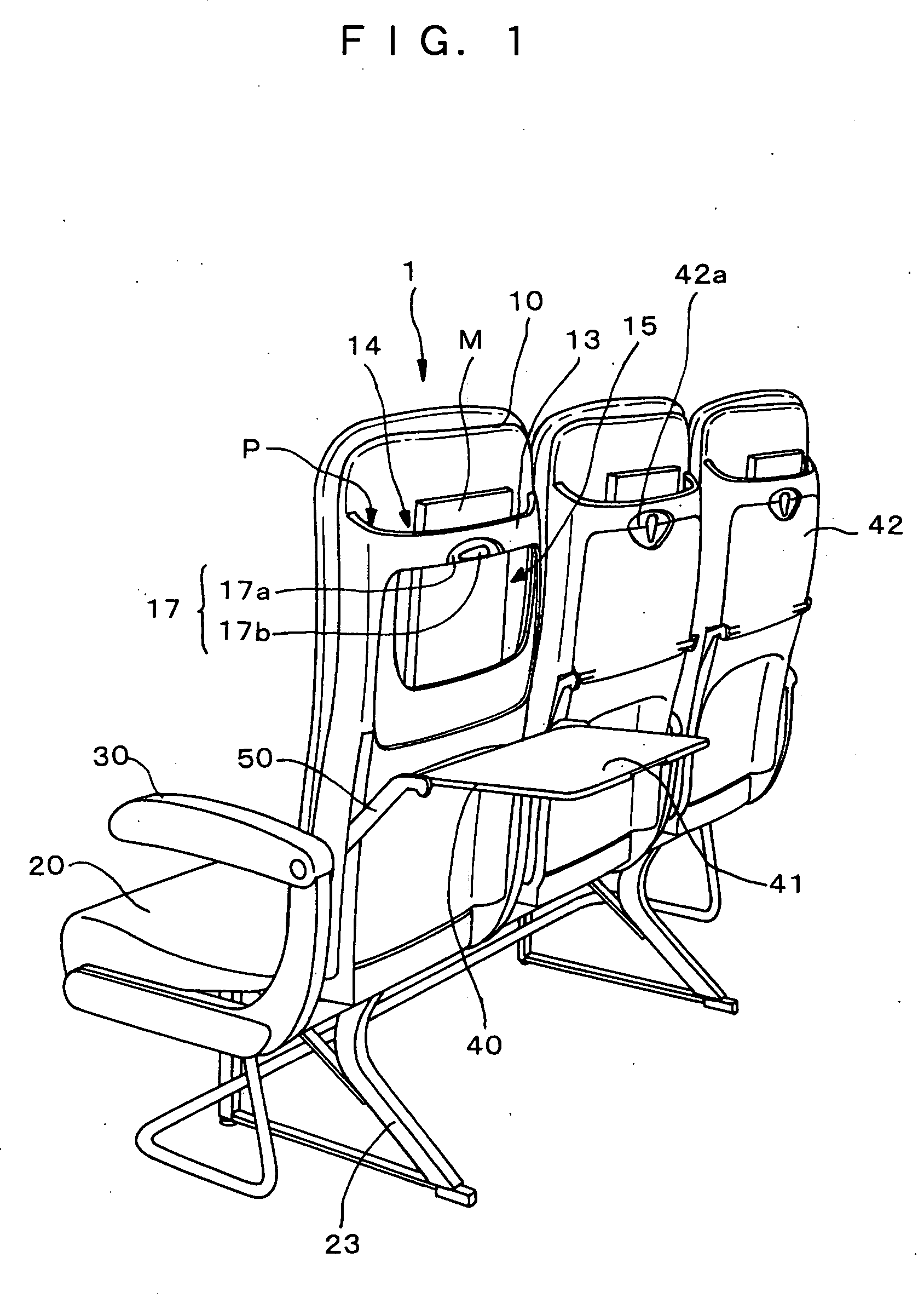
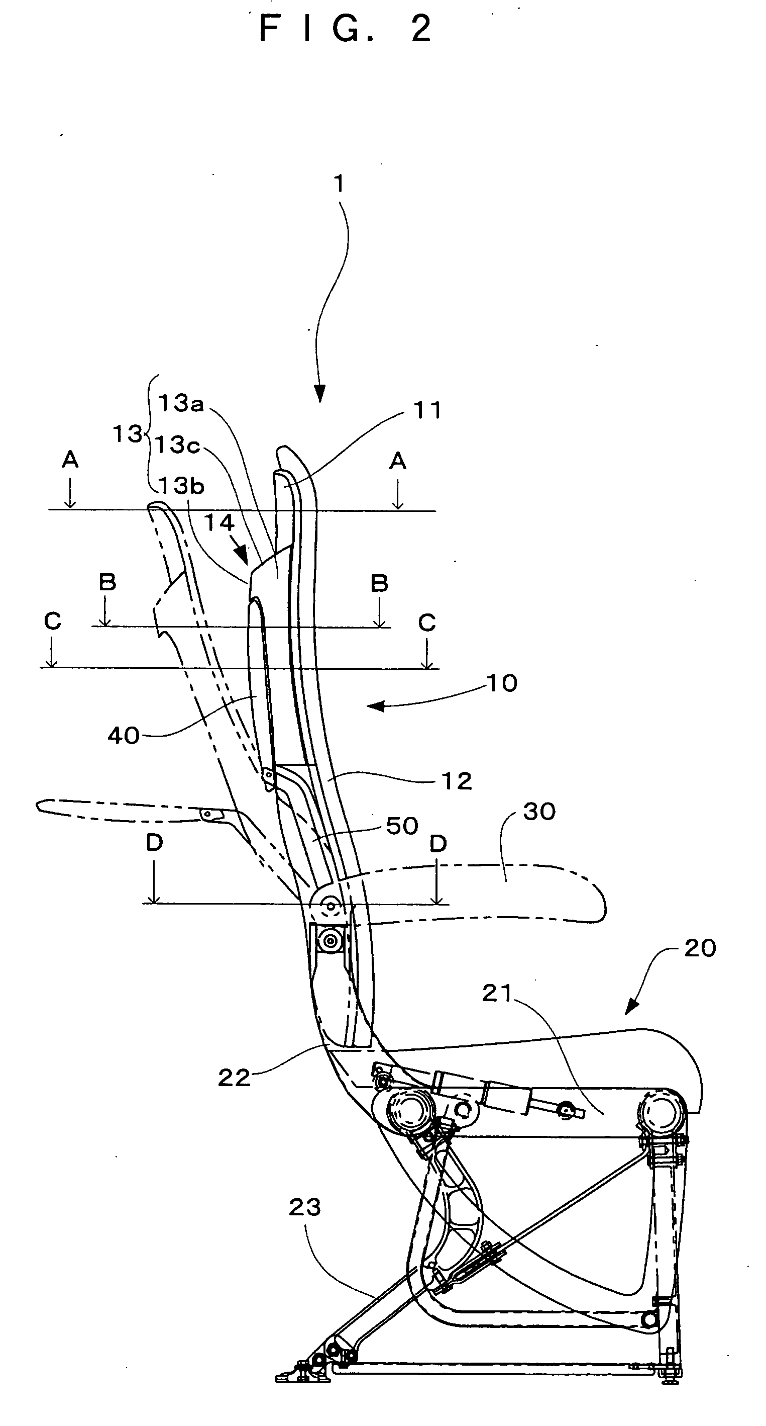
[0036]FIG. 1 is a perspective view of a three-person capacity aircraft seat that three aircraft seats are connected, pertaining to the present embodiment, when viewed from oblique rear, and FIG. 2 is a side view of the aircraft seat pertaining to the present embodiment.

[0037]The aircraft seat 1 is made up of a seat back 10, a seat bottom 20, an armrest 30, a table 40, and the like. The seat bottom 20 is provided on a bottom frame 21. This bottom frame 21 is connected to a base frame 22. This base frame 22 is supported by a leg part 23, and this leg part 23 is installed onto the floor of a passenger cabin of an aircraft.

[0038]The seat back 10 is made up of a back plate member 11 which is formed of a hard resin, a cushion 12 which is installed onto a front face 11a of th...


PUM


Abstract

An aircraft seat which can receive the load of a sitting person with only a back plate member, using no seat back frame, thus eliminating the need for sacrificing the sitting space, which results from the existence of the seat back frame, and at the same time, allowing the weight of the seat to be reduced, is provided. The aircraft seat (1) on which an aircraft passenger is to sit comprises a seat back (10) made up of a back plate member (11) that a cushion (12) is installed onto a front face (11a) thereof for receiving the back of a sitting person, and a reinforcing member (13) which is disposed on the rear face (11b) of the back plate member (11) for reinforcing the back plate member (11), and said back plate member (11) is formed in the shape of a curved surface which enhances the surface rigidity.

Description

TECHNICAL FIELD[0001]The present invention relates to an aircraft seat on which an aircraft passenger is to sit.BACKGROUND ART[0002]Conventionally, a structure which is common to vehicle seats, such as aircraft seats and automobile seats, is stated in Japanese Patent Laid-Open Publication No. 2001-057916. With this structure, to a leg part which is to be fixed to the floor of a vehicle, a base frame is fixed, and thereto a bottom frame and a seat back frame are connected. To the bottom frame configured in this way, a bottom cushion on which a sitting person is to sit is mounted, and to the seat back frame, a seat back cushion which can receive the back of a sitting person is mounted. The seat back cushion is mounted to a back plate member, and the seat back frame is mounted such that it surrounds the side edge part and the upper edge part of the back plate member.[0003]With the aircraft seat, the seat back frame is formed with a tube frame for reinforcing the back plate member. The ...

Claims


Application Information

Patent Timeline
IPC IPC(8): B64D11/06A47C7/02A47C7/40
CPCA47C7/40B60N2/686B60N3/004B64D11/064Y02T50/46B64D11/0649B64D11/0638B64D11/06Y02T50/40
Inventor ASAMI, BUNGOSUZUKI, KOHEI
Owner KI HOLDINGS
Learn More