
Network element and method for setting a power level in a wireless communication system

Active Publication Date: 2010-06-17
IP ACCESS LTD
View PDF5 Cites 32 Cited by
  • Summary
  • Abstract
  • Description
  • Claims
  • Application Information

AI Technical Summary

Benefits of technology

[0017]Accordingly, the invention seeks to mitigate, alleviate or eliminate one or more of the abovementioned disadvantages singly or in any combination.
[0021]In one optional embodiment of the invention, the transmitter may be arranged to transmit a request to the wireless communication unit for the wireless communication unit to perform and transmit the at least one signal quality measurement, for example a signal-to-noise (Ec:No) measurement, to the network element. In this manner, the network element may be able to determine whether to adjust a transmit power level by specifically requesting one or more wireless communication units to transmit signal quality criteria that represents their particular radio frequency environment at their geographical location. Thus, the network element may then adjust the transmit power level to assist the wireless communication unit's receiver and decoding process, as well as maintain a minimum interference on neighbouring cells.

Problems solved by technology

Thus, the coverage area of a single macro cell will inevitably overlap (and encompass) a coverage area of a large number of femto cells.
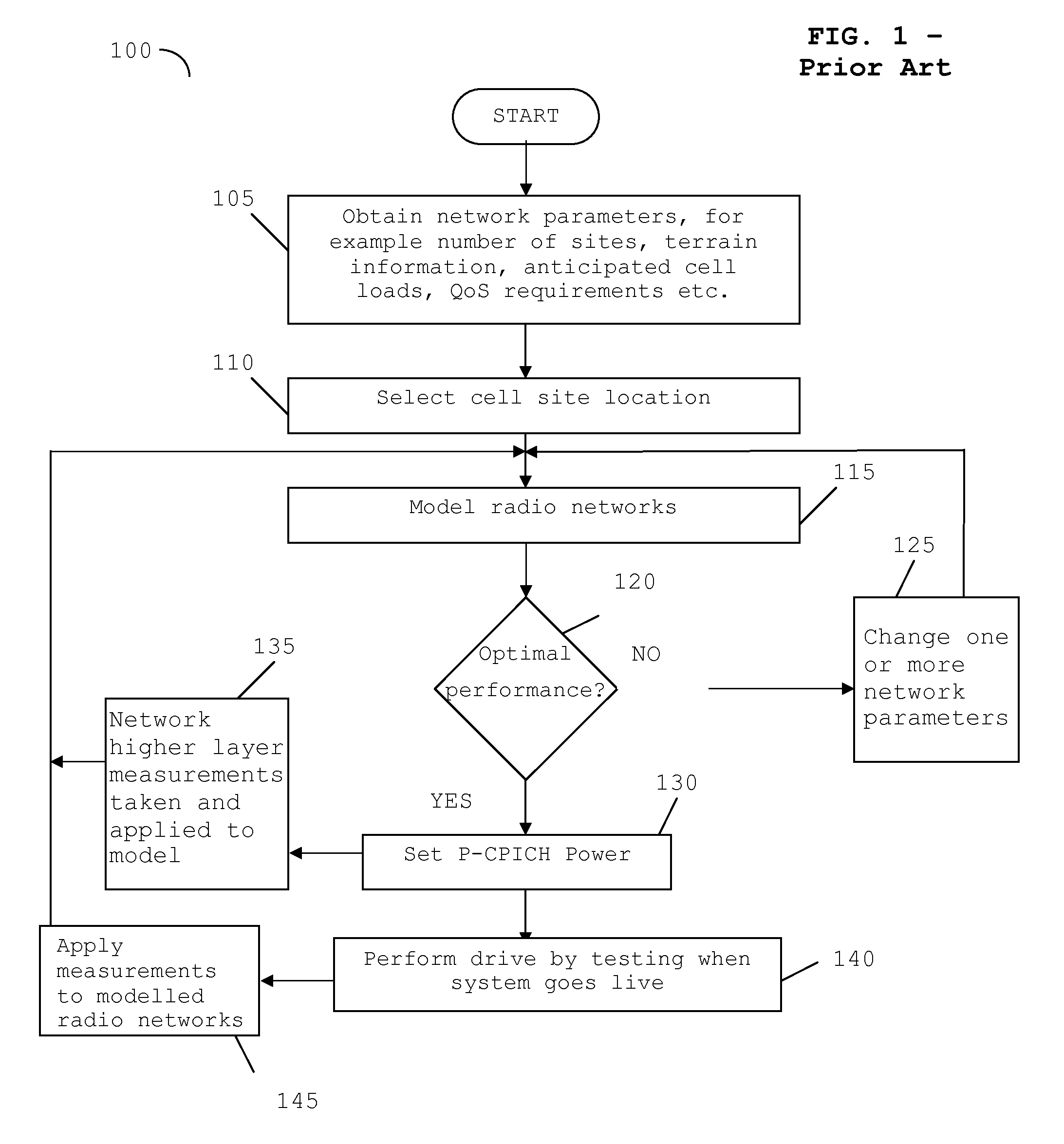
At present centralized radio network planning and techniques such as drive-by testing are utilized for the tuning of the P-CPICH power in the macro / micro cells, but will be unusable in a femto cell scenario.

Method used


Image

  • Network element and method for setting a power level in a wireless communication system
  • Network element and method for setting a power level in a wireless communication system
  • Network element and method for setting a power level in a wireless communication system

Examples


Embodiment Construction

[0030]Embodiments of the invention find particular applicability in a cellular communication system that supports a number of overlapping communication coverage areas, for example a communication system that comprises a combination of femto cells and macro cells. In a femto cell network it is known that there may be a very large number of femto cells per macro cell. Thus, the coverage area of a single macro cell will inevitably overlap coverage area of a large number of femto cells.

[0031]Those skilled in the art, however, will recognize and appreciate that the specifics of this example are merely illustrative of some embodiments and that the teachings set forth herein are applicable in a variety of alternative settings. For example, since the teachings described hereafter do not depend on a particular cellular communication network conforming to any specific standard, it is envisaged that the teachings and inventive concept described herein can be applied to any type of cellular com...


PUM


Abstract

A network element (230) for communicating with a wireless communication unit (214) in a communication cell (200) of a communication system (200) comprises a receiver arranged to perform a frequency sweep across a plurality of operational frequencies. Signal processing logic (255), operably coupled to the receiver, processes the received signals from the frequency sweep and providing an estimate of a level of interference at a number of frequency carriers of the swept frequencies. The signal processing logic (255) is capable of determining whether a transmit power level at a frequency selected from the processed frequency sweep satisfies at least one predetermined quality criterion of the communication system (200). A transmitter (270) is arranged, upon initial activation of the network element (230), to transmit to a wireless communication unit at the determined transmit power level.

Description

FIELD OF THE INVENTION[0001]The field of the invention relates to a cellular communication system, a communication network element and a method for setting a power level therein. In particular, the field of the invention relates to a network element and method for setting a power level in a wireless communication system that comprises femto-cells and macro-cells.BACKGROUND OF THE INVENTION[0002]Wireless communication systems, such as the 3rd Generation (3G) of mobile telephone standards and technology, are well known. An example of such 3G standards and technology is the Universal Mobile Telecommunications System (UMTS), developed by the 3rd Generation Partnership Project (3GPP) (www.3gpp.org).[0003]Typically, wireless communication units, or User Equipment (UE) as they are often referred to in 3G parlance, communicate with a Core Network (CN) of the 3G wireless communication system via a Radio Network Subsystem (RNS). A wireless communication system typically comprises a plurality ...

Claims


Application Information

Patent Timeline
IPC IPC(8): H04W72/00H04B17/00H04W52/24H04W52/32H04W52/50
CPCH04W52/241H04W52/325H04B17/327H04W84/045H04B17/318H04W52/50
Inventor PIERCY, NEIL PHILIPPOKHARIYAL, AKHILESHJOHNSON, NICHOLAS DOUGALL
Owner IP ACCESS LTD
Learn More