
Slide on connector for arch wire

a technology of connectors and arch wires, applied in the field of connectors, can solve the problems of affecting the mobility of the tongue, and being uncomfortable to wear

Inactive Publication Date: 2010-06-17
WILLIAMS MICHAEL O
View PDF22 Cites 15 Cited by
  • Summary
  • Abstract
  • Description
  • Claims
  • Application Information

AI Technical Summary

Benefits of technology

[0011]The present invention provides an improved pivotal mounting boss for attachment upon an arch wire as a component of an orthodontic treatment plan which may include front or rear orthodontic bands on a mandibular arch expander and a maxillary arch expander. The pivotal mounting boss includes a base casing with an opening formed therein that admits an arch wire. A screw is then threadedly engaged through the base casing. The screw passes through the base casing and contacts the arch wire for compression against the remainder of the base casing. Further, the opening can be pre-angulated to assist in root angulation when the arch wire is inserted.
[0016]Yet another object of the invention provides for a slide on connector for an arch wire that reduces the profile of the arch wire and related attachments outwardly of a patient's teeth.
[0018]Still another object of the invention is to provide a slide on connector for an arch wire that allows for low profile soldering or welding.
[0019]Yet another object of the invention is to provide a slide on connector for an arch wire that accommodates an arch wire for a mandibular expander thus improving patient comfort.
[0020]Another object of the invention is to provide a slide on connector for an arch wire that can accommodate a mandibular expander having a pre-torqued and pre-angulated opening in the base casing that assists in root angulation when the arch wire is inserted.
[0021]Another object of the invention is to provide a slide on connector for an arch wire that is readily manufactured, efficient to install, and well suited for its intended purposes.

Problems solved by technology

However, such mandibular arch expanders are rather bulky in design, uncomfortable to wear, impede tongue mobility, and interfere with oral hygiene.

Method used


Image

  • Slide on connector for arch wire
  • Slide on connector for arch wire
  • Slide on connector for arch wire

Examples


Embodiment Construction

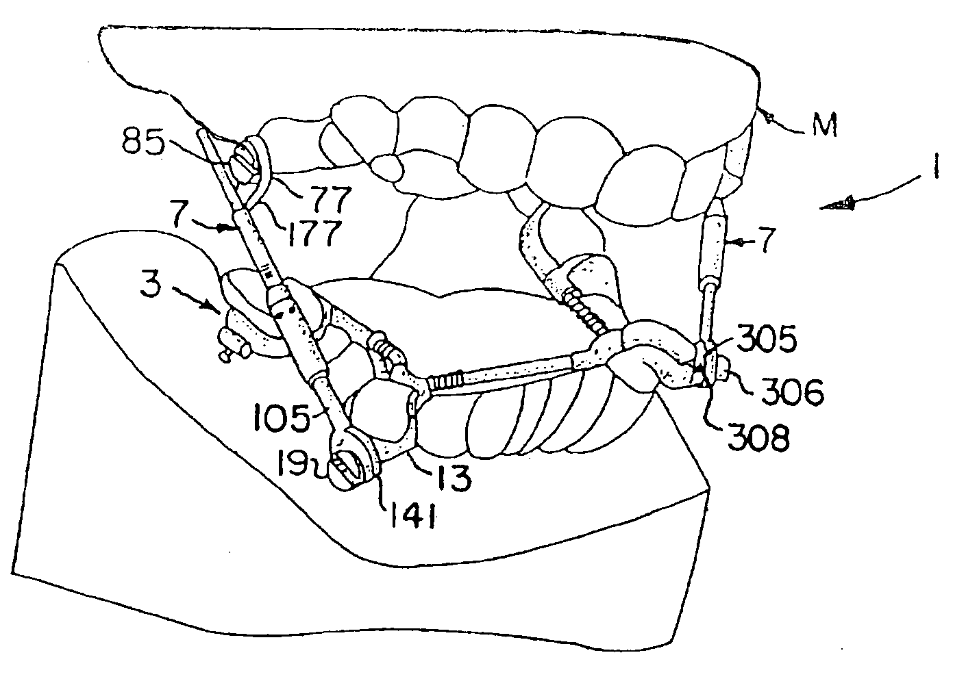
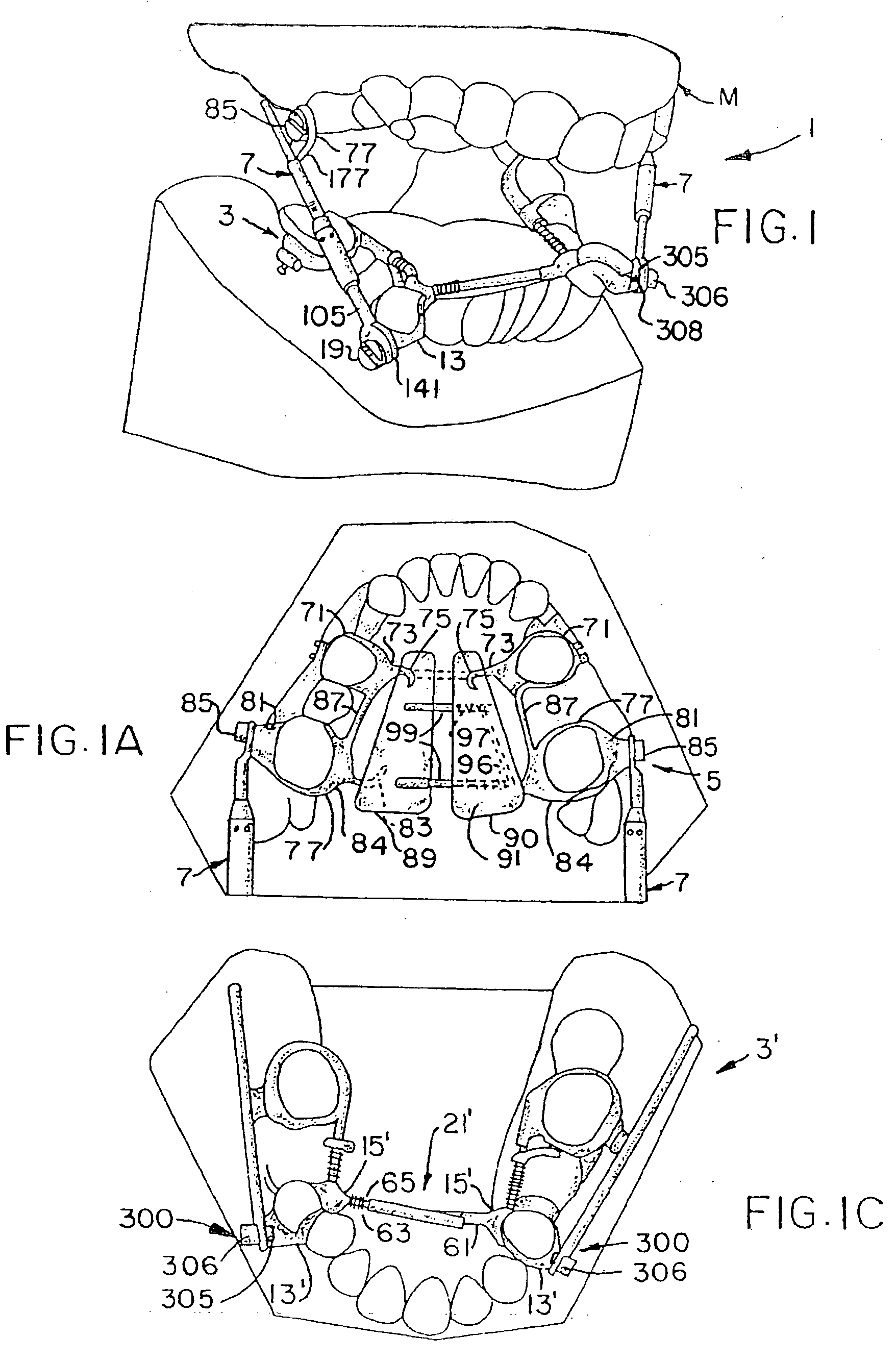
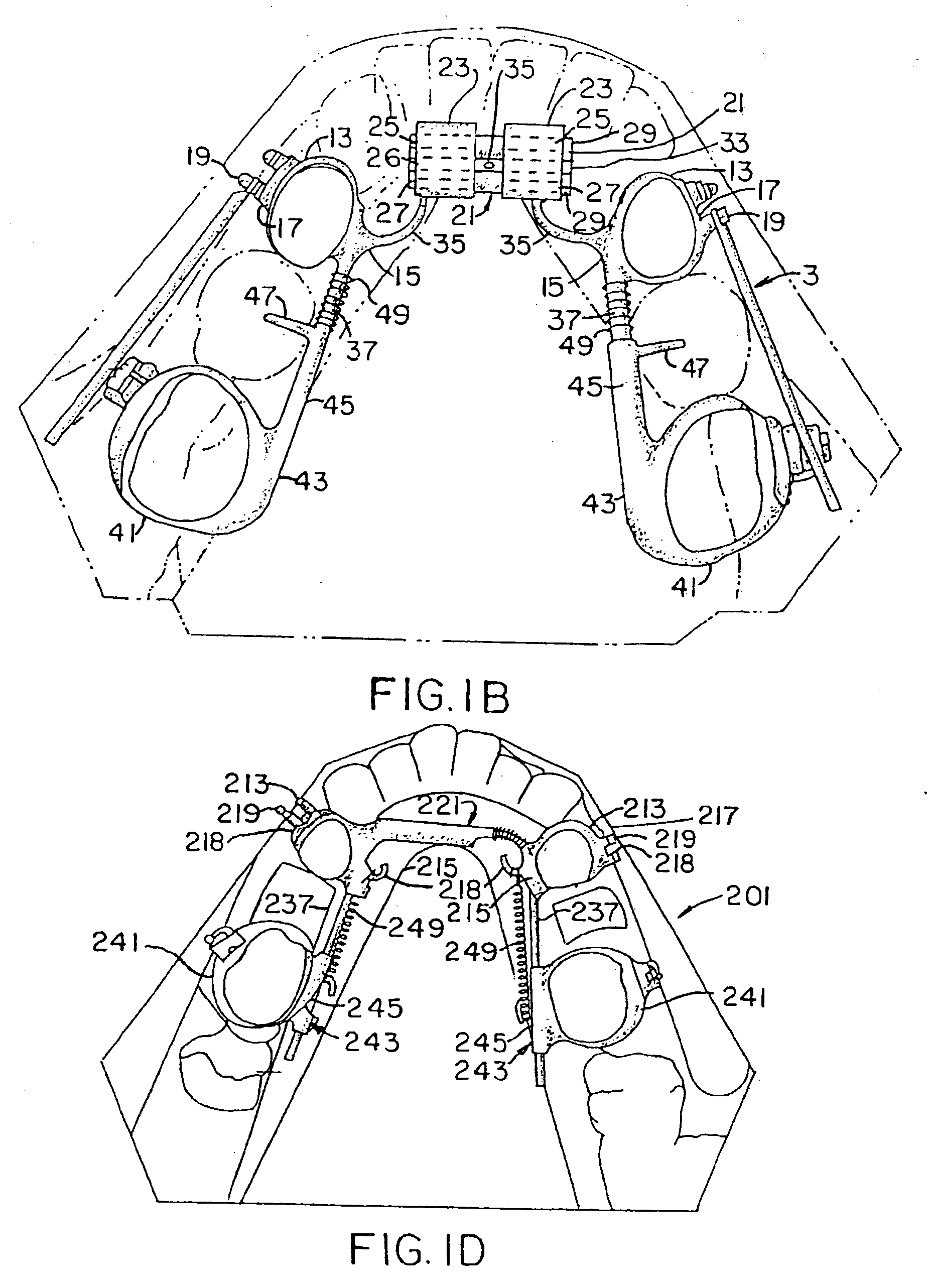
[0056]In referring to the drawings, FIGS. 1-1B, an orthodontic appliance 1 of the present invention is shown mounted in a mold M of a mouth. Although the appliance 1 is shown mounted in a mold, it will be appreciated that it is designed for use in a human mouth to increase the size of a child's mouth so that the child's permanent teeth will not be crowded when they erupt. This will reduce the need for extractions of permanent teeth. The appliance 1 includes a mandibular arch expander 3, a maxillary arch expander 5, and a pair of telescoping assemblies 7 which extend between and connect the mandibular and maxillary arch expanders 3 and 5, as described below.

[0057]The mandibular and maxillary arch expanders 3 and 5 are substantially the same as the arch expanders set forth in my above noted U.S. Pat. No. 5,645,422, which is incorporated herein by reference. The mandibular arch expander 3 (FIG. 1B) has a pair of spaced apart forward orthodontic bands 13 which are adapted to attach to t...


PUM


Abstract

A slide on connector for positioning upon an arch wire between the teeth of an orthodontic patent is provided. This connector works in conjunction with maxillary and mandibular arch expanders and other orthodontic appliances. The connector includes a base casing with a body segment and a base segment where both include a threaded bore. A screw is then threadedly engaged through the body and into the base segment. The base segment has tubes attached thereto for the insertion of an arch wire and the screw turns upon the arch wire for securement. The tubes can be preangulated to assist in root angulation or other orthodontia when the arch wire is inserted.

Description

CROSS REFERENCE TO RELATED APPLICATION[0001]This non-provisional application claims priority to the pending non-provisional application for patent Ser. No. 12 / 006,505 filed Jan. 3, 2008 which claims priority to the provisional application Ser. No. 60 / 881,330 filed on Jan. 19, 2007, and this application claims priority to the pending non-provisional application Ser. No. 11 / 480,681, filed Jul. 1, 2006 which claims priority to the non-provisional application for patent Ser. No. 10 / 439,638, filed May, 16, 2003, now U.S. Pat. No. 7,094,051, which is commonly owned by the same inventor, and which is a continuation-in-part of application Ser. No. 10 / 186,604, filed Jul. 2, 2002, now U.S. Pat. No. 6,877,982, which is a continuation-in-part of application Ser. No. 09 / 975,633, filed Oct. 12, 2001, now U.S. Pat. No. 6,719,557, and which is a continuation-in-part of application Ser. No. 09 / 750,527, filed Dec. 29, 2000, now U.S. Pat. No. 6,520,772, which is a continuation-in-part of application S...

Claims


Application Information

Patent Timeline
Patent Type & Authority Applications(United States)
IPC IPC(8): A61C7/12
CPCA61C7/00A61C7/36A61C7/12A61C7/282A61C7/10
Inventor WILLIAMS, MICHAEL O.
Owner WILLIAMS MICHAEL O
Learn More