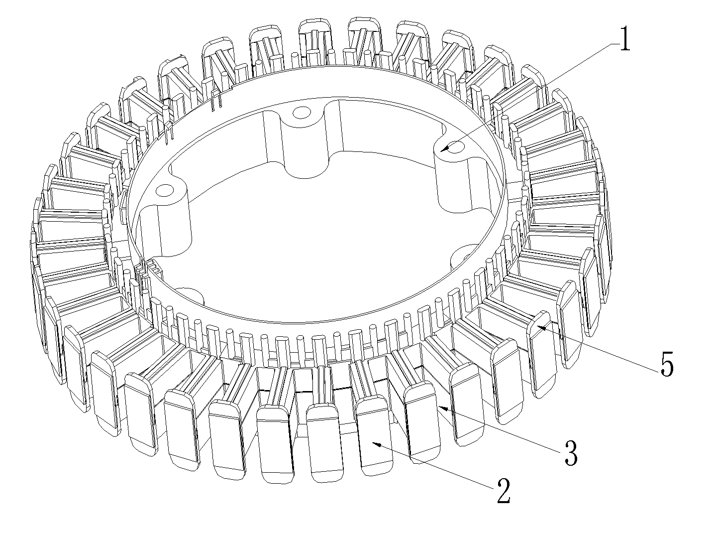
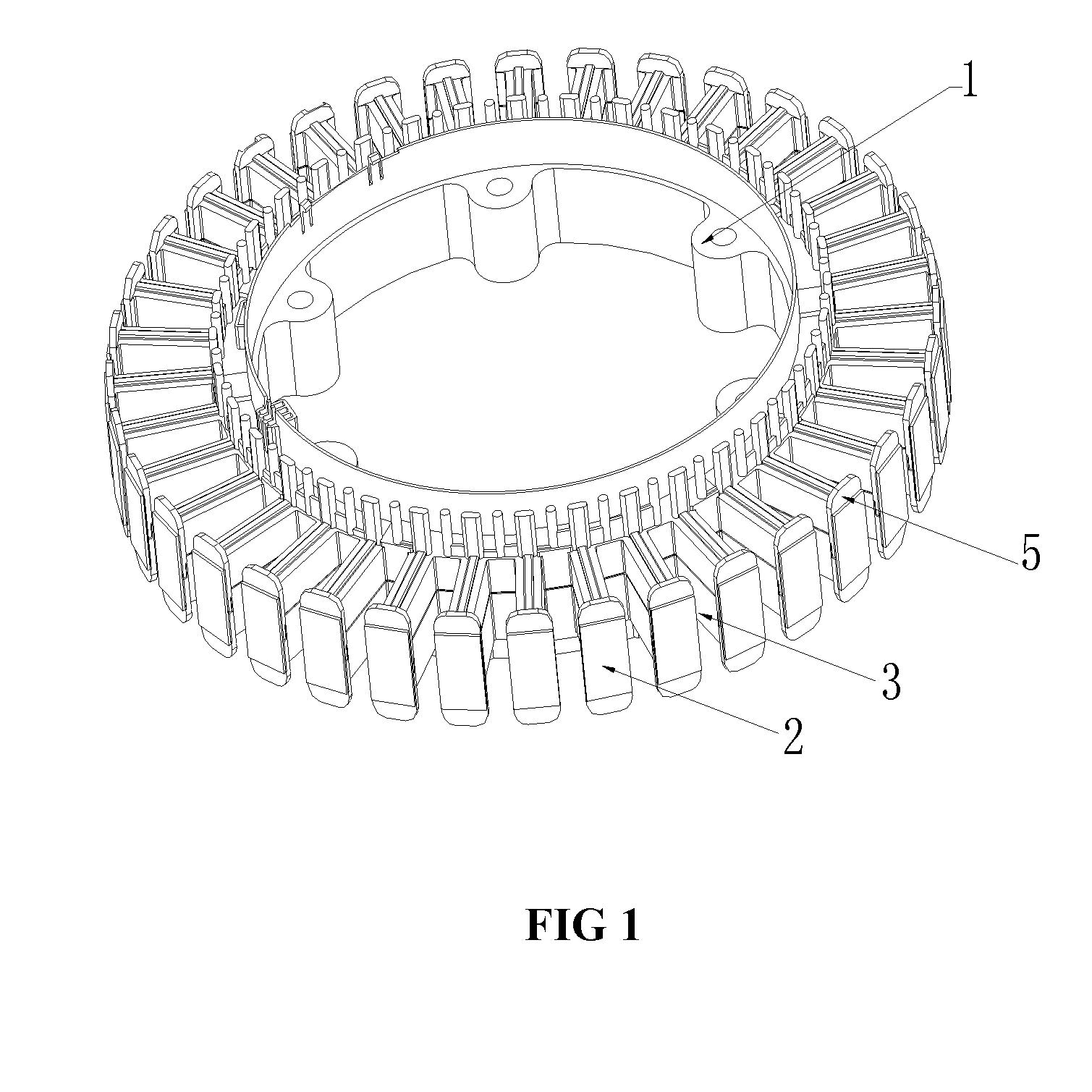
Stator and wire winding method therefor
a technology of motor stator and wire winding, which is applied in the direction of dynamo-electric machines, ac commutators, electrical apparatus, etc., can solve the problems of reducing the working life of the stator, and achieve the effects of long working life, small cogging torque, and smooth operation
- Summary
- Abstract
- Description
- Claims
- Application Information
AI Technical Summary
Benefits of technology
Problems solved by technology
Method used
Image

Examples
example 1
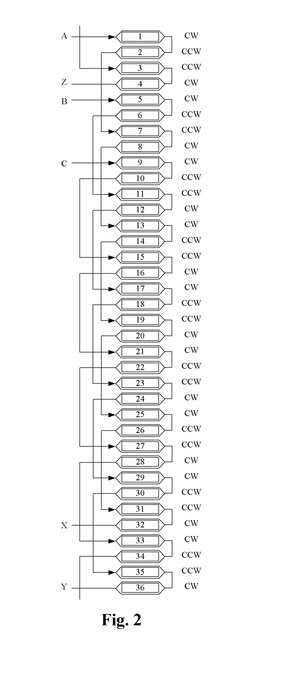
Three-phase Stator Winding
[0031]For a motor with a three-phase stator winding, a wire winding method comprises the following steps.
[0032]For U-phase winding with two ends A and X:
[0033]1) wrapping winding wires around the 1st tooth in the clockwise direction;
[0034]2) wrapping winding wires around the 2nd tooth in the anticlockwise direction;
[0035]3) crossing 4 sequential teeth and wrapping winding wires around the 7th tooth in the anticlockwise direction;
[0036]4) wrapping winding wires around the 8th tooth in the clockwise direction;
[0037]5) wrapping winding wires around the 13th tooth and the 14th tooth;
[0038]6) crossing 4 sequential teeth and wrapping winding wires around the 19th tooth and the 20th tooth;
[0039]7) wrapping winding wires around the 25th tooth and the 26th tooth; and
[0040]8) crossing 4 sequential teeth and wrapping winding wires around the 31th tooth and the 32th tooth.
[0041]For V-phase winding with two ends B and Y:
[0042]1) wrapping winding wires around the 3rd too...
example 2
Three-phase Stator Winding
[0059]For a motor with a three-phase stator winding, a wire winding method comprising the following steps:
[0060]For U-phase winding:
[0061]1) wrapping winding wires around the 1st tooth in the anticlockwise direction;
[0062]2) wrapping winding wires around the 2nd tooth in the clockwise direction;
[0063]3) crossing 4 sequential teeth and wrapping winding wires around the 7th tooth in the clockwise direction;
[0064]4) wrapping winding wires around the 8th tooth in the anticlockwise direction;
[0065]5) wrapping winding wires around the 13th tooth and the 14th tooth;
[0066]6) crossing 4 sequential teeth and wrapping winding wires around the 19th tooth and the 20th tooth;
[0067]7) wrapping winding wires around the 25th tooth and the 26th tooth;
[0068]8) crossing 4 sequential teeth and wrapping winding wires around the 31th tooth and the 32th tooth.
[0069]For V-phase winding:
[0070]1) wrapping winding wires around the 3th tooth in the anticlockwise direction;
[0071]2) wrap...
PUM
 Abstract
Description
Claims
Application Information
 - R&D
- Intellectual Property
- Life Sciences
- Materials
- Tech Scout
- Unparalleled Data Quality
- Higher Quality Content
- 60% Fewer Hallucinations
Browse by: Latest US Patents, China's latest patents, Technical Efficacy Thesaurus, Application Domain, Technology Topic, Popular Technical Reports.
© 2025 PatSnap. All rights reserved.Legal|Privacy policy|Modern Slavery Act Transparency Statement|Sitemap|About US| Contact US: help@patsnap.com