Eureka AIR delivers breakthrough ideas for toughest innovation challenges, trusted by R&D personnel around the world.

Synchronous machine

a synchronous machine and synchronous technology, applied in the field of electric machines, can solve the problems of large torque oscillation, inability to switch off the magnetic field of the permanent magnet machine, and inability to ensure the quality of the torque during normal fault-free operation, so as to achieve small cogging torque, reduce torque ripple, and improve reliability

Inactive Publication Date: 2013-05-07
ROBERT BOSCH GMBH
View PDF9 Cites 1 Cited by
  • Summary
  • Abstract
  • Description
  • Claims
  • Application Information

AI Technical Summary

Benefits of technology

[0010]When using a topology of an electrical machine having 12 stator teeth and 14 rotor poles, a very small cogging torque and little torque ripple were found. This topology makes it possible for the winding to be in the form of a single-tooth winding, thus avoiding the possibility of shorts being created at crossing points where stator coils cross over. This ensures greater reliability.
[0011]In particular, at least one of the stator teeth is not broadened in the tangential direction at its end facing the rotor. This topology allows the stator teeth of the electrical machine to be designed without a broadened tooth head, as a result of which the coil winding can be prefabricated and plugged onto the stator tooth. This considerably simplifies the production of an electrical machine such as this.
[0012]The electrical machine preferably has a single-tooth winding configuration, thus making it possible to avoid coil windings of different phases crossing over.

Problems solved by technology

However, in the case of electronically commutated synchronous motors, harmonics result in so-called harmonic torques, which can lead to major oscillations in the torque.
These braking torques occur since, in contrast to machines with electrically excited fields, it is impossible to switch off the magnetic field in machines with permanent-magnet excitation.
Electrical machines having 12 stator teeth and 8 rotor poles are already known, but these do not ensure adequate torque quality during normal fault-free operation.
Furthermore, an electrical machine having 18 stator teeth and 8 rotor poles is known, but this has the disadvantage that the electrical machine has a distributed winding in which the coil windings of different phases cross in the end winding, and coil sides of different phases are located in the stator slots.
Split stators lead to asymmetries because of dimensional tolerances, as a result of which poor cogging torques can occur.

Method used


Image

  • Synchronous machine
  • Synchronous machine
  • Synchronous machine

Examples


Embodiment Construction

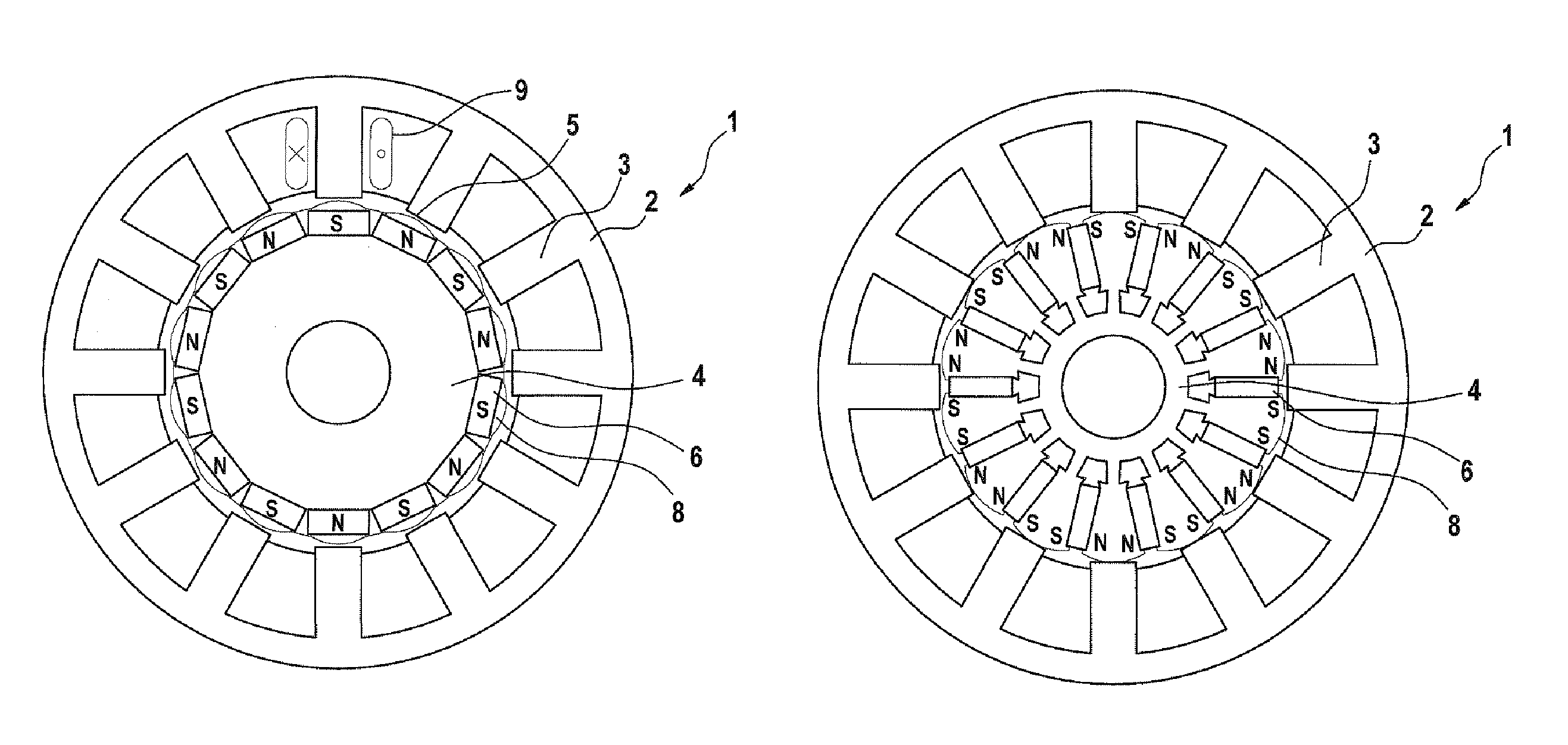
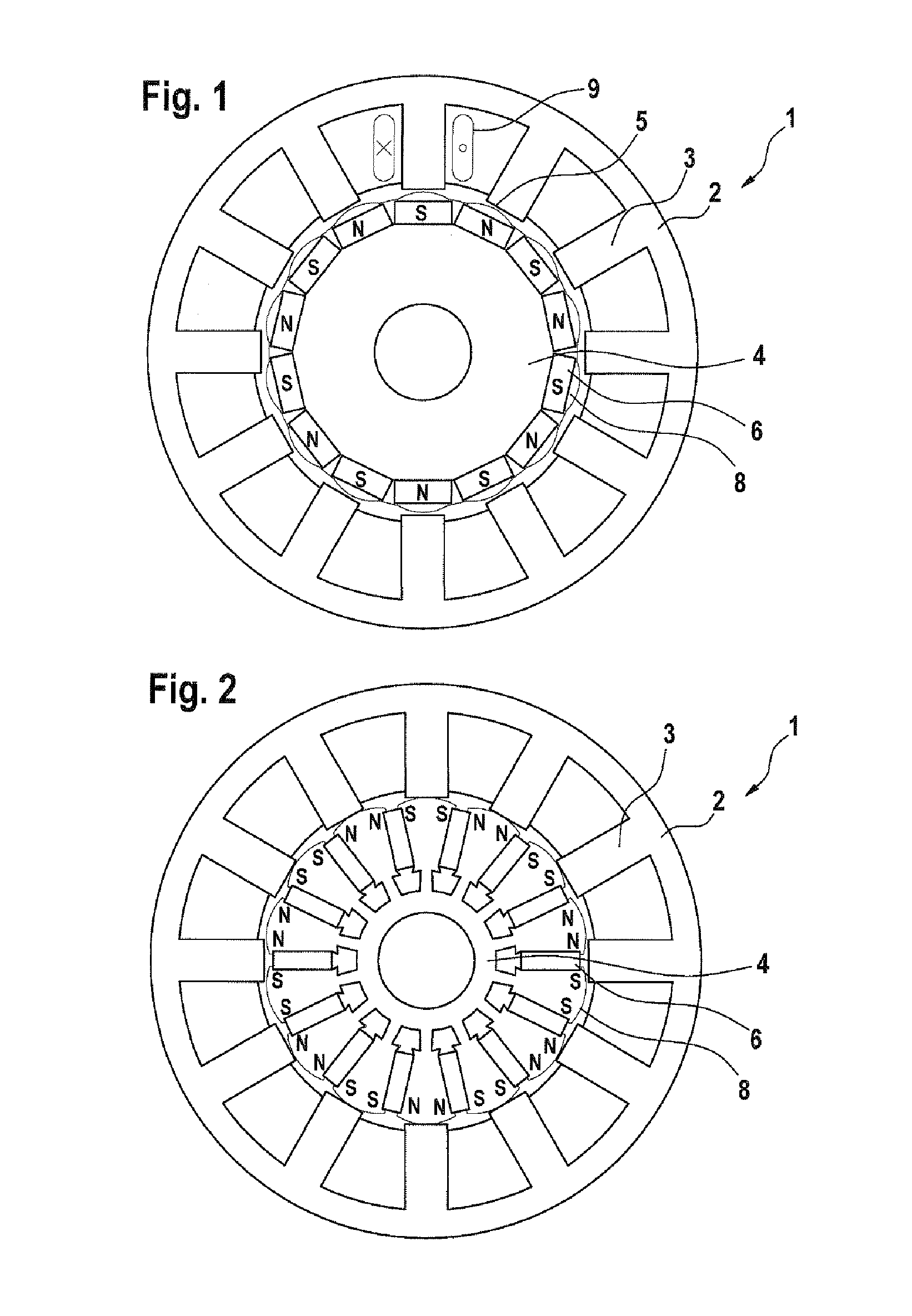
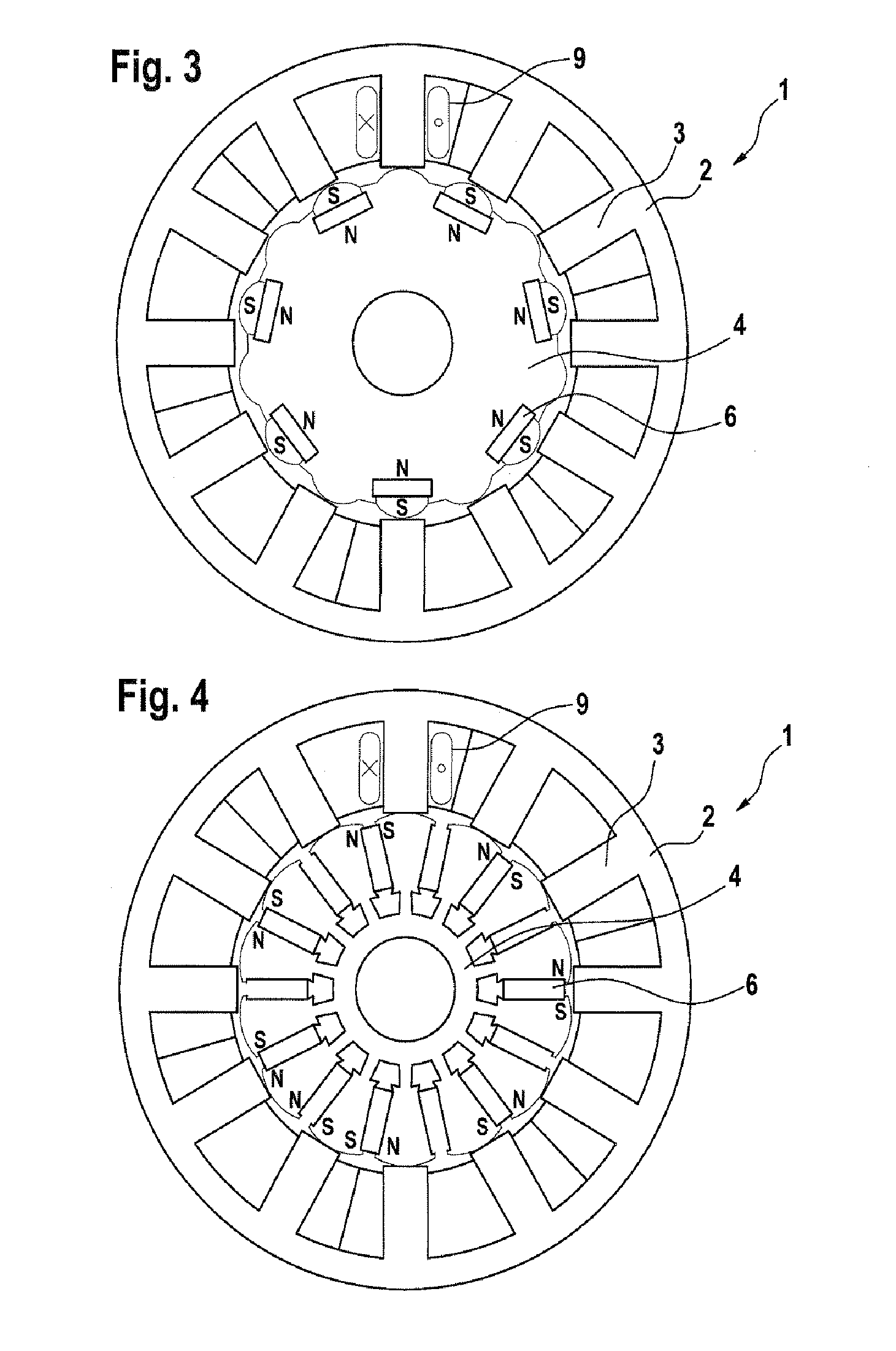
[0036]FIG. 1 shows a cross section through an electrical machine 1. The electrical machine has a stator 2, which surrounds a rotor 4 which can rotate about a center axis M. In the illustrated exemplary embodiment, the electrical machine is in the form of a synchronous machine.

[0037]The stator 2 has 12 stator teeth 3 which, projecting in the radial direction from a stator body of the stator 2, are directed inward in the direction of the rotor 4. This means that the stator teeth 3 are aligned in the direction of the center axis M of the electrical machine 1. The stator teeth 3 are uniformly separated from one another in the tangential direction, that is to say they are arranged with the same offset angle, and in the interior of the stator body.

[0038]The rotor 4 is arranged such that it can rotate about the center axis M and has the permanent magnets 6. The permanent magnets 6 form rotor poles 8 and are arranged such that their magnetic poles run in the radial direction. Adjacent perma...


PUM


Abstract

The invention relates to an electric machine (1) comprising: —a rotor (4) having 14 rotor poles (8) which is arranged rotatably about a central axis and—a stator (2) having 12 stator teeth (3) which project in a radial direction relative to the central axis from the stator (2) in the direction of the rotor (4), characterized in that each of the stator teeth (3) is surrounded by a stator coil (9) which surrounds only one of the stator teeth.

Description

BACKGROUND OF THE INVENTION[0001]The invention relates to an electrical machine having 12 stator teeth and 14 rotor poles, in particular for use in electrical steering aids.[0002]In the case of electrical drives for steering systems with electromechanical assistance for use in motor vehicles, it is necessary for the fluctuations in the drive torque produced in the shaft to be as small as possible. Electrically commutated synchronous motors with permanent magnet excitation are normally used for applications such as these, because these motors have advantages owing to their power density, their efficiency and their control capability.[0003]However, in the case of electronically commutated synchronous motors, harmonics result in so-called harmonic torques, which can lead to major oscillations in the torque. Drives such as these must therefore be designed to reduce these harmonics as much as possible or to keep their effects on the torque profile as small as possible. Furthermore, in th...

Claims


Application Information

Patent Timeline
Patent Type & Authority Patents(United States)
IPC IPC(8): B62D5/04
CPCH02K1/146H02K1/276H02K21/16H02K1/2746
Inventor FEUERROHR, LIN
Owner ROBERT BOSCH GMBH
Why Eureka
Eureka Blog
Learn More