
Outboard motor

a technology for outboard motors and motors, which is applied in the direction of marine propulsion, vessel construction, combustion air/fuel air treatment, etc., can solve the problem that the air in the upper space extending above the fan cannot be efficiently sucked by the fan, and achieve the effect of efficiently preventing the discharge of air in the engine compartmen

Inactive Publication Date: 2010-06-17
HONDA MOTOR CO LTD
View PDF3 Cites 6 Cited by
  • Summary
  • Abstract
  • Description
  • Claims
  • Application Information

AI Technical Summary

Benefits of technology

[0013]According to the present invention, the inlet passage of the air discharge passage provided with the fan to discharge air to the outside of the engine compartment of the outboard motor is formed in the upper space of the engine compartment and opens upward. Hot air that has worked for cooling the engine can be efficiently sucked by the fan from the upper space in which hot air collects of the engine compartment, and the hot air can be efficiently discharged to the outside of the engine compartment, i.e., to the outside of the outboard motor. Consequently, the engine compartment can be efficiently ventilated, the engine can be effectively cooled by ventilation air, and temperature rise of the engine compartment can be effectively suppressed.
[0029]Since the exit ventilation structure including the fan and the case forming the air discharge passage, and the air guide structure for guiding air that has worked for cooling the generator to the inlet ventilation passage of the air discharge passage are formed integrally, the generator, the fan and the inlet ventilation passage can be arranged close to each other. Therefore, the diffusion of the discharged air in the engine compartment can be efficiently prevented, and the air guide structure for guiding the discharged air to the fan and the exit ventilation structure can be formed in small, lightweight structures.

Problems solved by technology

If air in the engine compartment flows upward, through an air passage having an inlet opening facing downward, into a fan for forcing air out of the engine compartment, air in an upper space extending above the fan cannot be efficiently sucked by the fan.

Method used


Image

  • Outboard motor
  • Outboard motor
  • Outboard motor

Examples


Embodiment Construction

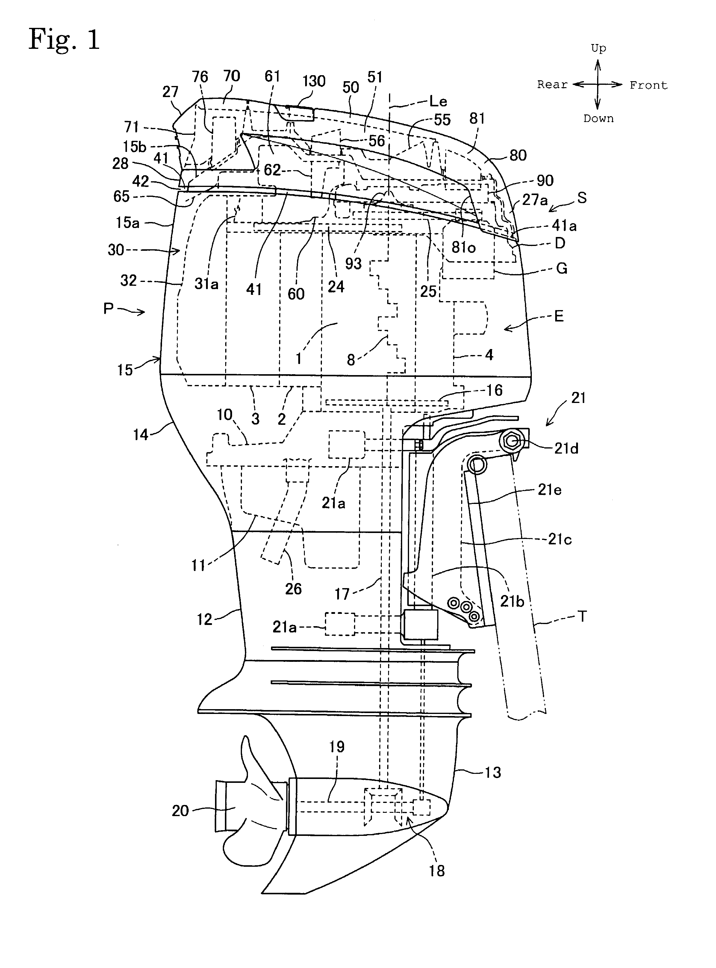
[0046]An outboard motor S in a preferred embodiment of the present invention will be described with reference to FIGS. 1 to 16.

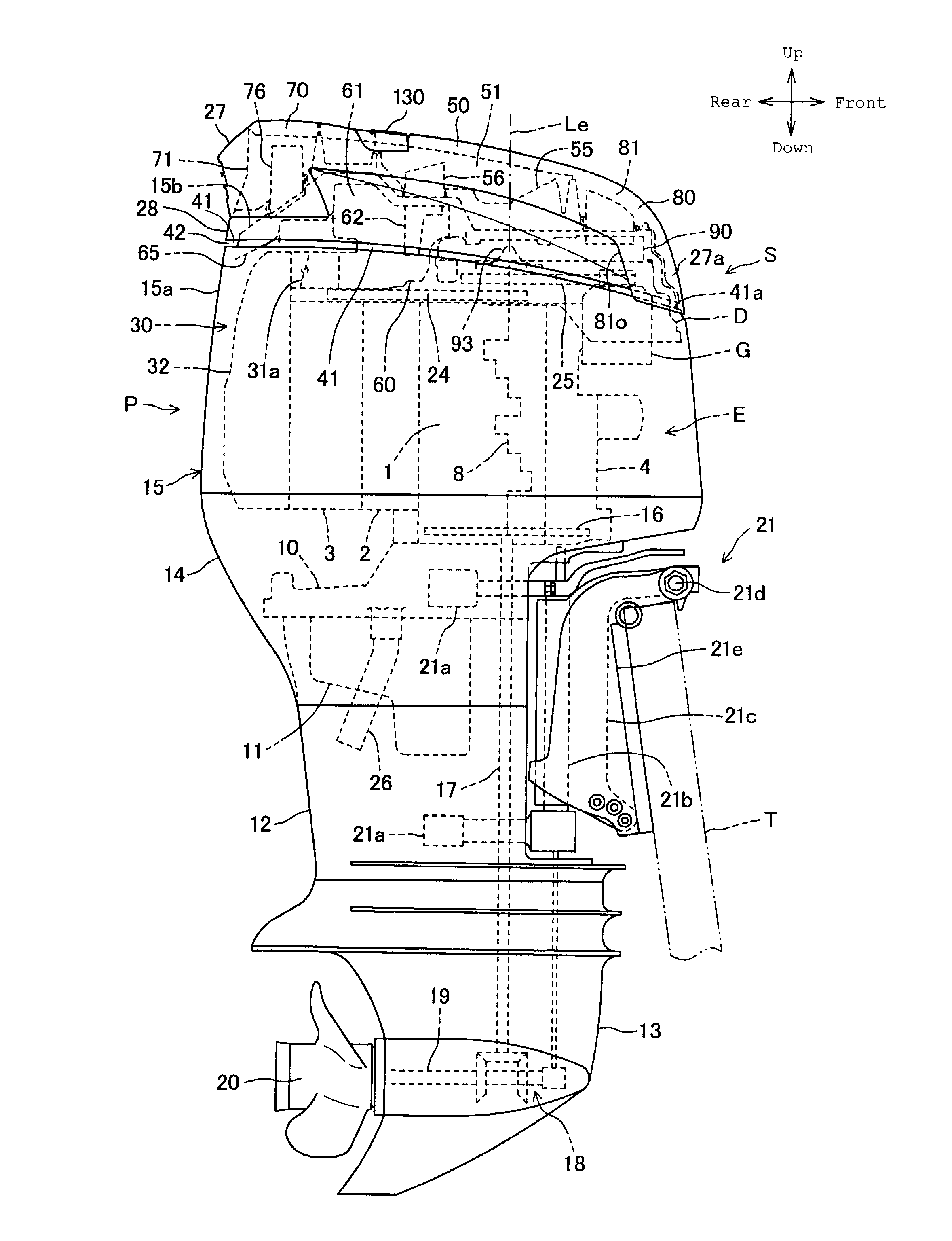
[0047]Referring to FIG. 1, the outboard motor S as a ship-propulsion machine includes a power unit P, a propeller 20, namely, a thrust-producing member, driven by the power unit P, and a holding device 21 for holding the power unit P on a transom of a hull T of a boat. The power unit P includes an internal combustion engine E, a transmission for transmitting the output power of the internal combustion engine E to the propeller 20, covers including an engine cover 15 forming an engine compartment R (FIG. 2) for holding the internal combustion engine E therein, an upstream intake silencer 50 through which intake air for the engine E is taken in, and a ventilation system for ventilating the engine compartment R.

[0048]Referring to FIG. 2, the internal combustion engine is a vertical V-type four-stroke water-cooled six-cylinder internal combustion engine provided...


PUM


Abstract

An outboard motor has an engine, an engine cover forming an engine compartment for holding the engine therein, a ventilation system with an outer outlet ventilation space through which air in the engine compartment flows to the outside of the engine compartment, and a generator. The ventilation system includes a case disposed in the engine compartment and forming an air discharge passage leading to the outer outlet ventilation space. A fan is placed in the air discharge passage to deliver air by pressure from the engine compartment to the outer outlet ventilation space. The air discharge passage has an inlet ventilation passage formed in an upper space in the engine compartment and opening upward. The engine compartment holding the engine therein can be efficiently ventilated, and ventilation air can effectively cool the engine and can effectively suppress temperature rise in the engine compartment.

Description

BACKGROUND OF THE INVENTION[0001]1. Field of the Invention[0002]The present invention relates to an outboard motor including an engine, an engine cover forming an engine compartment for holding the engine therein, and a ventilation system for ventilating the engine compartment.[0003]2. Description of the Related Art[0004]A known outboard motor disclosed in, for example, JP 9-254883A includes an engine, an engine cover forming an engine compartment for holding the engine therein, a generator disposed in the engine compartment, and a ventilation system for discharging air in the engine compartment to the outside of the engine compartment through an air exit passage opening to the outside of the engine compartment.[0005]Another known outboard motor disclosed in JP 2002-240790A includes a generator disposed in an engine compartment and having a housing provided with an inlet passage through which cooling air for cooling the generator flows into the generator, and an air outlet through w...

Claims


Application Information

Patent Timeline
IPC IPC(8): F01P1/02F02M35/02B63J2/00
CPCF01P2001/005F01P2050/12F02B61/045F02M35/1288F02M35/10295F02M35/168F02M35/1211F02M35/10268
Inventor SAKATA, SHIGEKAZUYAZAKI, MAKOTOIDE, SHINICHI
Owner HONDA MOTOR CO LTD
Learn More