
Canal dilation device

a dilation device and canal technology, applied in balloon catheters, vaccination/ovulation diagnostics, surgery, etc., can solve the problems of affecting the safety of patients, so as to prevent the leakage of such fluids and minimize the risk of tissue trauma

Inactive Publication Date: 2010-06-10
LEVEL THREE INNOVATIONS
View PDF4 Cites 16 Cited by
  • Summary
  • Abstract
  • Description
  • Claims
  • Application Information

AI Technical Summary

Benefits of technology

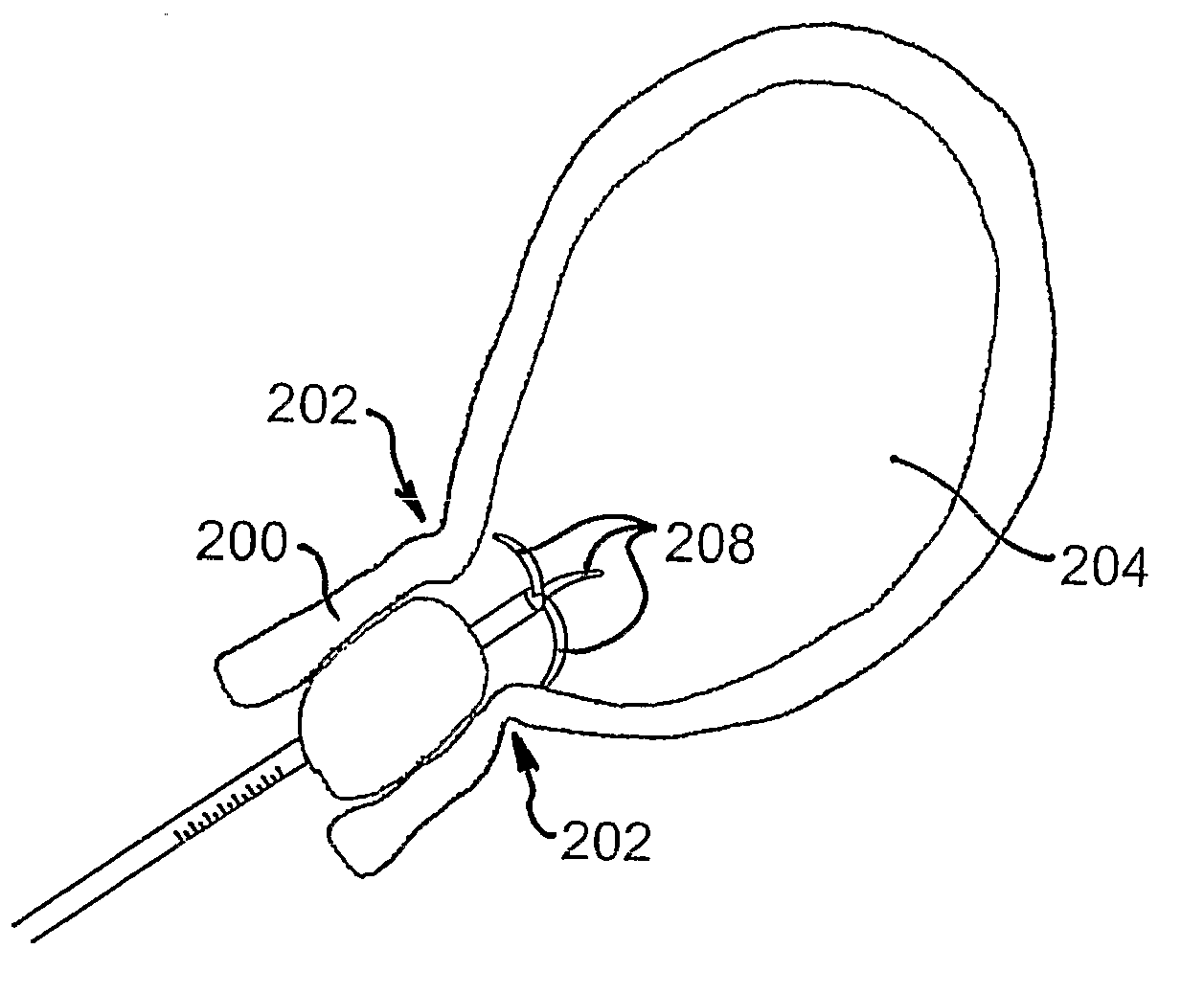
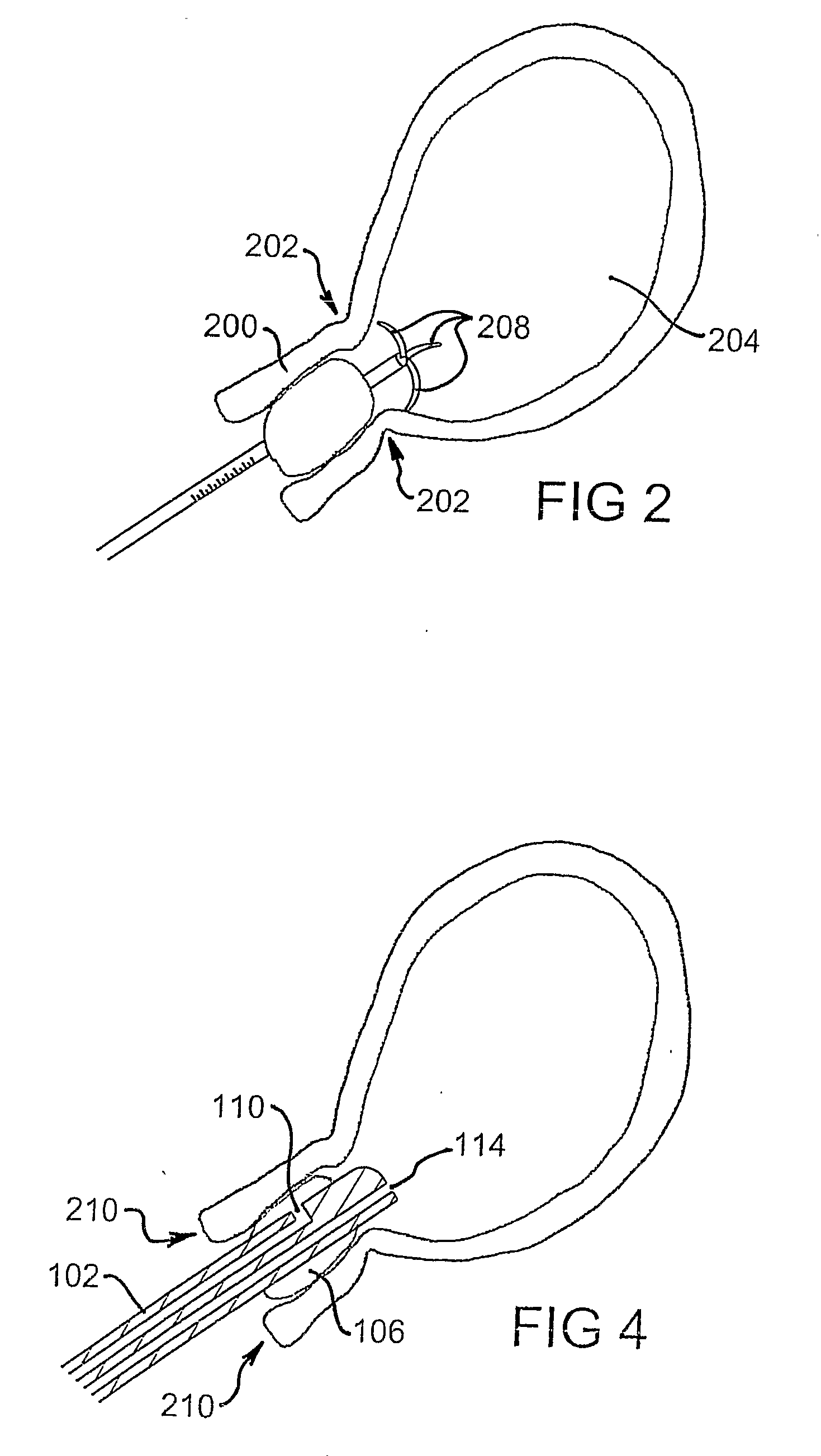
[0012]In a preferred embodiment, the device includes markings along a length of the elongate member. The markings indicate a depth of insertion of the elongate member into the cervical canal and / or uterine cavity for use in uterine sounding. The markings may extend along a length of the elongate member beginning just inside the external cervical os when the elongate member has been inserted into the cervical canal and extending proximally. Alternatively, the markings may extend along a length of the elongate member, beginning at the distal tip of the device. The markings may extend along a defined length of the member or alternatively, along the entire length of the member. Preferably, the markings extend approximately 10 cm, 12 cm or 14 cm from the distal tip of the elongate member to facilitate sounding of the uterus during use although these dimensions are not to be taken as limiting.
[0032]The seal formed by the inflatable body overcomes difficulties associated with other methods of hydrodilation in which fluid leakage is common at the catheter-cervix interface. Embodiments of the present invention provide a useful alternative approach to fallopian tube hydrodilation and other diagnostic tests of fallopian tube patency.

Problems solved by technology

Repeated cervical entry using Hagar dilators of increasing size is associated with cervical trauma, tears and bleeding as larger dilators are forced through the cervical canal.
Also, use of Hagar dilators and cervical sounds is associated with accidental uterine perforation.
Uterine perforation can result in complications such as haemorrhage and infection, sometimes necessitating additional procedures such as laparoscopy and laparotomy to correct the complications.

Method used


Image

  • Canal dilation device
  • Canal dilation device
  • Canal dilation device

Examples


Embodiment Construction

[0044]The anatomy of the cervix (including the cervical canal) varies considerably between females of different ages and before and after natural childbirth. The endocervical canal (hereinafter referred to as the cervical canal) which is the passageway between the external cervical os (which projects into the vagina) and internal cervical os (which projects into the uterine cavity) varies in length and width although it is typically 5 mm to 10 mm wide and 20 mm to 50 mm long in women.

[0045]Enlarging or increasing the cervical canal is also known as “cervical dilation” and it is often necessary prior to performing a range of intrauterine procedures such as curettage, hysteroscopy, biopsy, termination of pregnancy, visualisation of the uterus, and dilation of the fallopian tubes. Other procedures in which cervical dilation may be required include placement or removal of intrauterine devices, induction of labour and endometrial biopsy to name a few. The present invention provides a new...


PUM


Abstract

A device for enlarging a canal of a human or animal subject includes an elongate member having a first lumen extending therein and an inflatable body toward a distal end of the elongate member. The inflatable body is deliverable, in an uninflated or deflated state, to a location substantially within the canal prior to inflation. The first lumen is in communication with the inflatable body via one or more channels therebetween. In use, the first lumen is in communication, toward a proximal end, with an inflation system for delivering fluid to inflate the inflatable body and thereby enlarging the canal. The device may include markings for sounding of e.g. uterine depth. The device may also include one or more projections, or other structure providing tactile cues during positioning of the device within the canal and these may also be configured to aid in removal of cells from a tissue wall.

Description

FIELD OF THE INVENTION[0001]The present invention relates to a device for dilating a canal, such as a cervical canal or urethra, of a human or animal subject. The invention also relates to a method and system for doing the same.BACKGROUND TO THE INVENTION[0002]Dilation of the cervix and cervical canal is performed in procedures where access to and / or instrumentation of the interior of the uterus is required. Dilation typically involves use of Hagar dilators, a set of curved stainless steel rods each having a different cross-sectional diameter ranging from 2 Hagar (2 mm) to 14 Hagar (14 mm). To dilate the cervix, a small Hagar dilator is inserted through the external cervical os and into the cervical canal. It is then removed and a larger dilator is inserted. This process is repeated using progressively larger diameter dilators until the desired amount of cervical dilation is achieved.[0003]Dilation of the cervix is commonly accompanied by sounding of the uterus to determine uterine ...

Claims


Application Information

Patent Timeline
IPC IPC(8): A61M29/02A61B10/02A61M25/10
CPCA61M2025/0008A61M25/10
Inventor LEE, STEPHENTAN, JASON JIT-SUN
Owner LEVEL THREE INNOVATIONS
Learn More