
Squeezing gun for two-part medical viscous fluid

a technology of viscous fluid and squeezing gun, which is applied in the direction of impression caps, instruments, teeth caps, etc., can solve the problems of inability to properly squeeze viscous fluid in the position, difficulty in user squeezing viscous fluid with high viscosity, and inability to properly squeeze viscous fluid, etc., to achieve the effect of easily detaching the double cartridge and squeezing stiff viscous fluid in the double cartridg

Inactive Publication Date: 2010-06-10
SEIL GLOBAL
View PDF7 Cites 50 Cited by
  • Summary
  • Abstract
  • Description
  • Claims
  • Application Information

AI Technical Summary

Benefits of technology

[0007]This invention is to solve the problem mentioned above. This invention has the technological project to solve the problem as follows. First, stiff viscous fluid in double cartridge can be squeezed easily by only a little power that presses push button that supplies power to driving motor by enabling horizontal scroll bar to be moved horizontally with electric power of driving motor where decelerator is installed. Second, viscous fluid can be injected conveniently in the position that is targeted by detaching double cartridge from squeezing gun easily.
[0010]This invention regarding squeezing gun for two-part medical viscous fluid has the advantage in squeezing stiff viscous fluid in double cartridge easily by a little power that presses push button of switch shape which supplies power to driving motor by enabling horizontal scroll bar to be moved horizontally with electric power of driving motor where decelerator is installed.
[0011]Besides, this invention enables viscous fluid to be injected correctly to the targeted place by easily detaching double cartridge from squeezing gun as horizontal scroll bar can be retracted rapidly due to elasticity of spring when opening cover installed upper side of squeezing gun that can be opened or closed in hinged mode after stopping squeezing viscous fluid in double cartridge.

Problems solved by technology

It has been difficult for user to squeeze viscous fluid with high viscosity by only the power of index finger and squeezing requires considerable power.
Besides, viscous fluid has not been squeezed correctly in the position that is intended to be targeted because edge of double cartridge is shaken from which viscous fluid is squeezed.

Method used


Image

  • Squeezing gun for two-part medical viscous fluid
  • Squeezing gun for two-part medical viscous fluid
  • Squeezing gun for two-part medical viscous fluid

Examples


Embodiment Construction

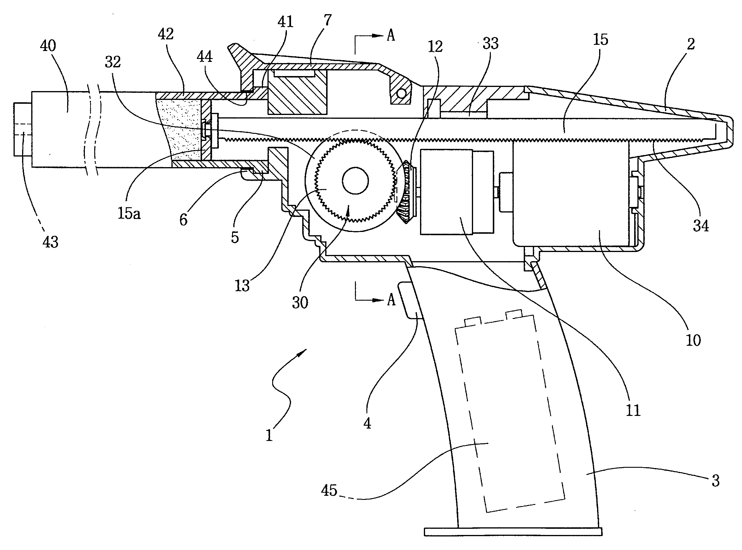
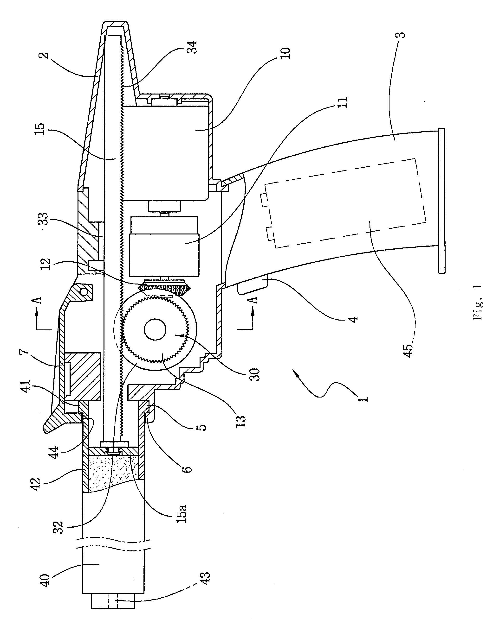
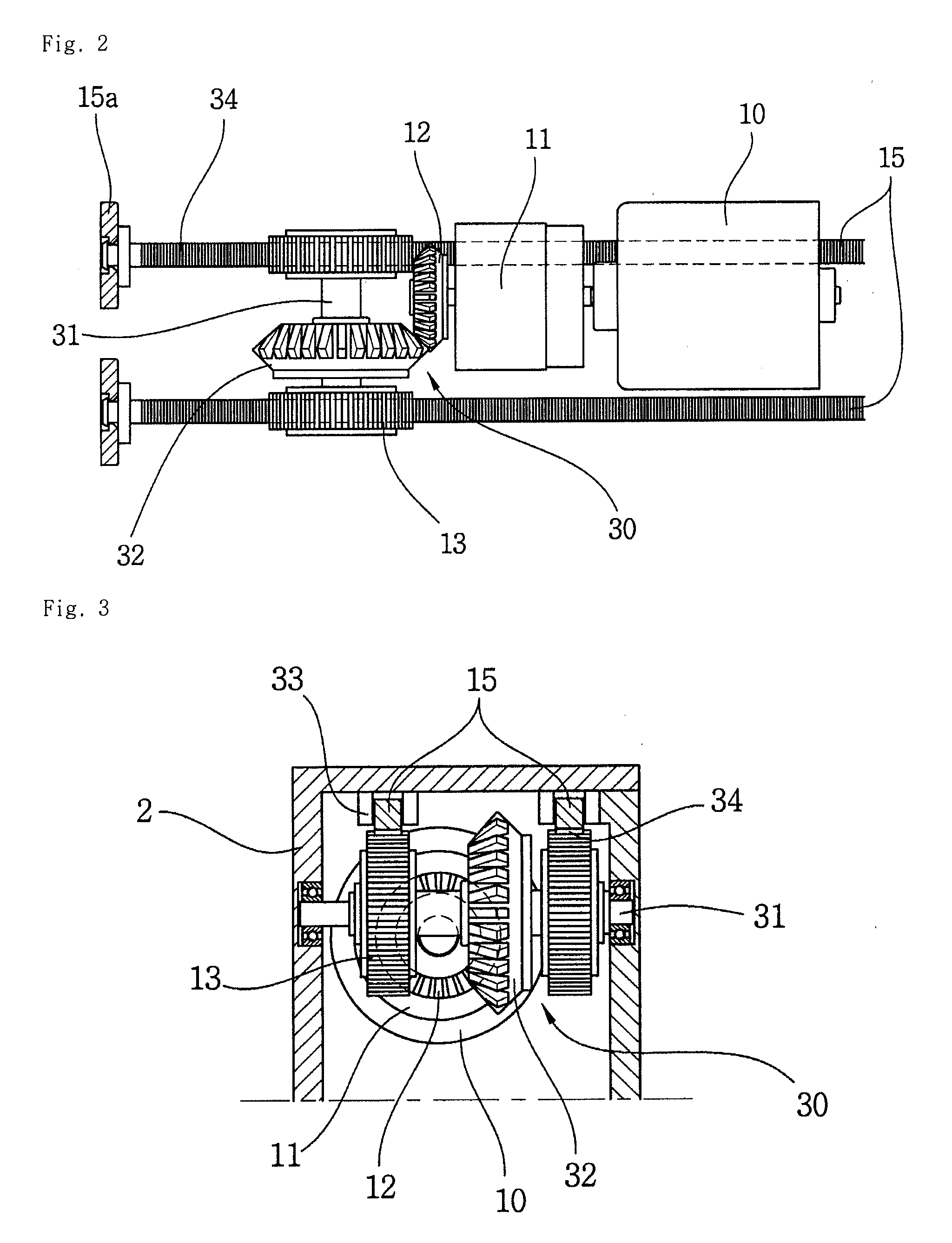
[0023]Explanation of squeezing gun for two-part medical viscous fluid according to this invention referring to FIG. 1 and FIG. 10 is as follows.

[0024]This invention is to squeeze viscous fluid contained in double cartridge with the power of driving motor 10 by installing driving motor 10 on squeezing gun 1 which has the shape of pistol where double cartridge 40 is installed in removable mode.

[0025]Forward area of double cartridge 40 mentioned above is equipped with stout divider 43 and a pair of tubes 42 whose rear side is open is combined in one body and at the rear side of double cartridge where a pair of tubes are combined in one body, flange part 41 that is designed to install double cartridge 40 at the forward area of squeezing gun 1 in removable mode is formed protruded outward and in each tube 42 mentioned above, different kinds of viscous fluid is filled.

[0026]As shown in FIG. 1 and FIG. 3, case main body 2 whose forward are is open is installed on the upper side of handle 3...


PUM


Abstract

This invention is about squeezing gun for two-part medical viscous fluid that squeezes two different kinds of medical viscous fluid simultaneously that are contained in double cartridge where two tubes are combined in one body and when explained in more detail, this invention is to squeeze simultaneously two kinds of medical viscous fluid that are contained in double cartridge while two horizontal scroll bars are moving horizontally as driving power of driving motor is being reduced when push button of squeezing gun which has the shape of pistol is pressed.

Description

BACKGROUND OF THE INVENTION[0001]1. Field of the Invention[0002]This invention is about squeezing gun for two-part medical viscous fluid that extrudes two different kinds of medical viscous fluid at the same time that are contained in double cartridge where two tubes are combined into one body and when explained in more detail, this invention is to extrude simultaneously two kinds of medical viscous fluid (hereinafter call viscous fluid) that are contained in double cartridge while two horizontal scroll bars are moving horizontally as driving power of driving motor is being reduced when button of squeezing gun which has the shape of pistol is pushed.[0003]2. Description of the Prior Art[0004]Existing squeezing gun for two-part medical viscous fluid has had the shape of pistol overall and in the case that users squeeze viscous fluid in double cartridge which has been installed in cartridge insertion edge of squeezing gun, users should squeeze simultaneously two different kinds of vis...

Claims


Application Information

Patent Timeline
IPC IPC(8): A61C5/08B01F15/02A61C5/62A61C5/68
CPCA61C5/062A61C5/068B05C17/0133A61M5/19A61M2005/3152A61C9/0026B05C17/00553A61C5/62A61C5/68A61M5/20A61M5/14
Inventor AN, IM JUN
Owner SEIL GLOBAL
Learn More