
Sound volume correcting device, sound volume correcting method, sound volume correcting program and electronic apparatus

Inactive Publication Date: 2010-06-10
SONY CORP
View PDF13 Cites 15 Cited by
  • Summary
  • Abstract
  • Description
  • Claims
  • Application Information

AI Technical Summary

Benefits of technology

[0019]It is desirable to provide a sound volume correcting device and a sound volume correcting method, which can reduce an unpleasant feeling by making a wobble in output sound volume level at a level varying point not marked even when the level of an input audio signal greatly varies.
[0023]Accordingly, when the gain-controlled main first component signal and the other component audio signals other than the first component are auditorily reproduced, the wobble in sound volume level of the main first component signal is masked by the reproduced sound of the other component audio signals other than the first component due to the auditory combination thereof. Accordingly, the wobble in sound volume level at the level varying point is not marked, thereby reducing the unpleasant feeling.
[0024]When an audio signal which is obtained by adding the gain-controlled main first component signal to the other component audio signals other than the first component is output as the volume-corrected audio output signal, the wobble in sound volume level at the level varying point is not marked due to the same masking operation, thereby reducing the unpleasant feeling.
[0025]According to the above-mentioned embodiment of the invention, since the main first component signal and the other component audio signals other than the first component are output in different gain control ways, the wobble in sound volume level at the level varying point where the level of the input audio signals greatly varies is not marked, thereby reducing the unpleasant feeling.

Problems solved by technology

However, for example, when the channel is switched in receiving a television broadcast, when plural input devices are switched in an AV center, and when CM breaks or scenes are changed, a great level of difference may occur in the audio signals before and after the switch or change.
In this way, when the level of the input audio signal varies greatly, it is difficult to completely suppress the rapid variation in audio signal gain at the level varying point, and the output sound volume level wobbles at the level varying point, thereby giving an unpleasant auditory feeling to listeners.
Particularly, in the above-mentioned sound volume correcting method, since the gains of the entire audio signals are uniformly controlled, there is a problem that the unpleasant feeling resulting from the wobble in sound volume level at the rapid varying point is marked.

Method used


Image

  • Sound volume correcting device, sound volume correcting method, sound volume correcting program and electronic apparatus
  • Sound volume correcting device, sound volume correcting method, sound volume correcting program and electronic apparatus
  • Sound volume correcting device, sound volume correcting method, sound volume correcting program and electronic apparatus

Examples


first embodiment

Sound Volume Correcting Device

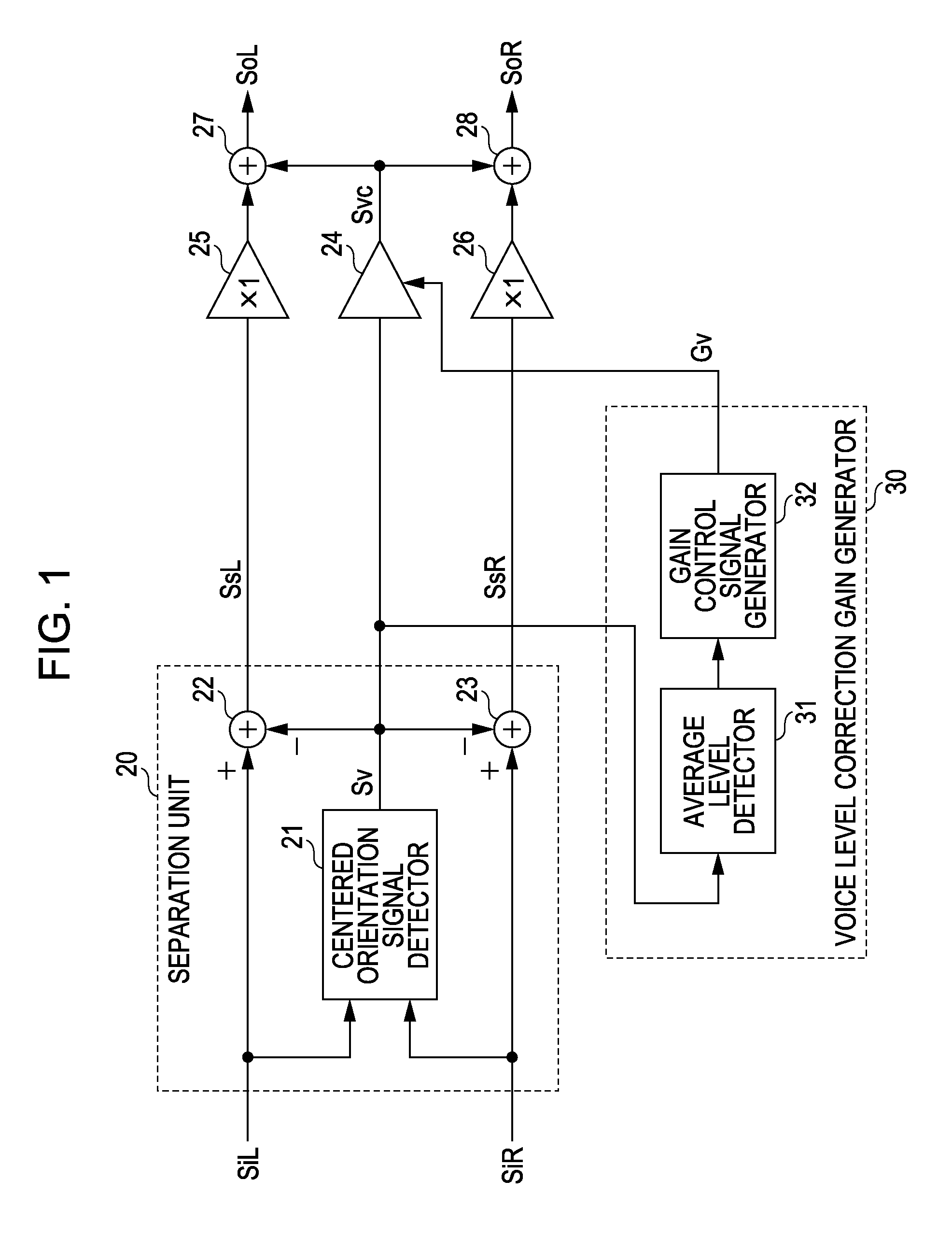
[0062]FIG. 1 is a block diagram illustrating the entire configuration of the sound volume corrector 18 as the sound volume correcting device according to a first embodiment of the invention.

[0063]In the first embodiment, the input audio signals are two left and right channel input audio signals. A main first component signal is a signal (hereinafter, referred to as “main voice signal”) containing a voice component as a main component out of the two left and right channel input audio signals. The other audio component other than the first component is a so-called live sound other than the main voice signal of the two left and right channel input audio signals. The signal containing the live sound component as a main component is hereinafter referred to as “main live sound signal”.

[0064]As shown in FIG. 1, in the first embodiment, the two left and right channel input audio signals SiL and SiR are supplied to a separation unit 20 separating the main voice ...

second embodiment

Sound Volume Correcting Device

[0128]The above-mentioned first embodiment employs the gain control way that the sound volume of the main live sound signal is not corrected. However, for example, when the level variation of the input audio signal due to the switching of channel is great, it may be preferable that the gain of the main live sound signal is controlled along with the main voice signal. A second embodiment of the invention can cope with this case.

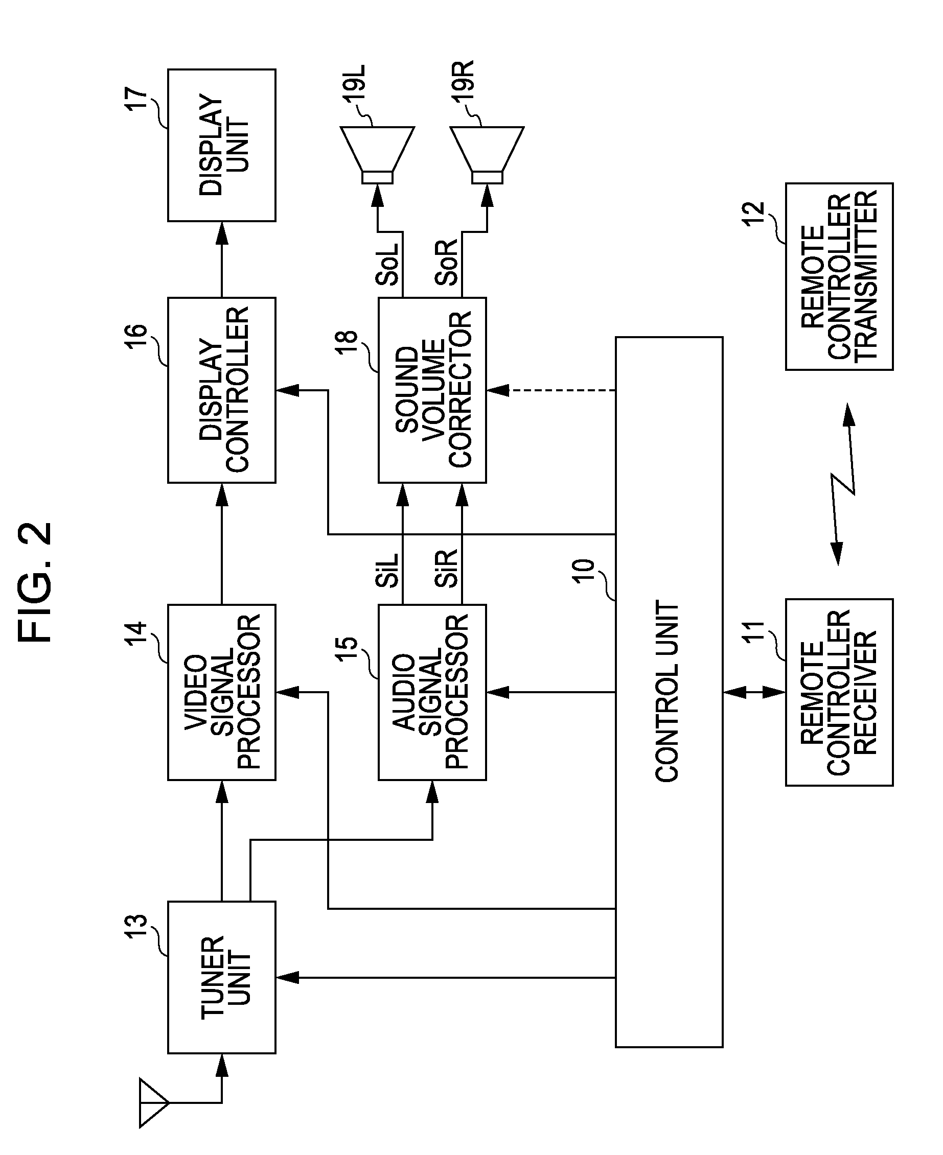
[0129]In the second embodiment described below, the sound volume correcting device is applied to the sound volume corrector 18 of the television broadcast receiver shown in FIG. 2, similarly to the first embodiment.

[0130]FIG. 14 is a block diagram illustrating the entire configuration of the sound volume corrector 18 according to the second embodiment. In FIG. 14, the same elements as the sound volume corrector 18 according to the first embodiment shown in FIG. 1 are referenced by the same reference numerals and signs.

[0131]In the...

first example

[0141]When the level variation of the input audio signal or the level variation of the main voice signal Sv is great and only the output level of the main voice signal Sv is controlled in gain to a constant level, the balance for the original input audio signal may deteriorate, thereby giving the unpleasant feeling.

[0142]The first example is to improve the above-mentioned problem. FIG. 15 is a diagram illustrating the configuration of the live sound level correction gain generator 40 in the first example. In the first example, the live sound level correction gain generator 40 includes a gain value switching table unit 41.

[0143]The gain value switching table unit 41 serves to receive the gain control signal Gv of the main voice signal Sv as an input signal and to output the gain control signal Gs of the main live sound signals SsL and SsR, and includes a gain value switching table memory (not shown).

[0144]FIG. 16 is a diagram illustrating an example of gain value switching table info...


PUM


Abstract

A sound volume correcting device includes: a first component gain control unit configured to control a gain of a main first component signal, which contains a part of a plurality of audio components as a main component, out of input audio signals including the plurality of audio components and outputting the main first component signal; a first component gain control signal generator configured to generate a first component gain control signal for allowing the first component gain control unit to control the gain of the main first component signal in a first gain control way; and an other component output unit configured to output other audio components other than the first component of the input audio signals in a second gain control way different from the first gain control way.

Description

BACKGROUND OF THE INVENTION[0001]1. Field of the Invention[0002]The present invention relates to a sound volume correcting device, a sound volume correcting method, and a sound volume correcting program, which can be suitably used in a sound output unit of an electronic apparatus such as a television broadcast receiver.[0003]2. Description of the Related Art[0004]When a broadcast channel received by a television broadcast receiver is switched or when plural input devices are switched in an AV center of an audio-visual (AV) system, an output sound volume may be greatly changed due to a level difference between contents.[0005]In this case, it is necessary for a user to adjust the sound volume using a remote controller or the like so as to obtain his preferred sound volume and thus may find it troublesome.[0006]Even with the same contents (for example, on the same broadcast channel or during the same broadcast program), the output sound volume varies depending on a variation between co...

Claims


Application Information

Patent Timeline
IPC IPC(8): H03G3/00
CPCH04S7/00H04S2400/13H04S2400/05
Inventor NOGUCHI, MASAYOSHI
Owner SONY CORP
Learn More