
Geothermal heating and cooling management system

a technology of geothermal heating and cooling management system, applied in the direction of thermal-pv hybrid energy generation, lighting and heating apparatus, greenhouse gas reduction, etc., can solve the problems of power conversion components also needing to be preheated, the management may be difficult, and the cooling capacity of a conventional thermal management system

Inactive Publication Date: 2010-06-10
GENERAL ELECTRIC CO
View PDF7 Cites 19 Cited by
  • Summary
  • Abstract
  • Description
  • Claims
  • Application Information

AI Technical Summary

Benefits of technology

"The present patent application provides a geothermal heating and cooling system for a power conversion system within an enclosure. The system includes a heat exchanger, pipes positioned in the ground, and a heat transfer medium circulating between the heat exchanger and the pipes. This system can effectively control the temperature of the power conversion system, improving its performance and reliability. The patent also describes a method of using the geothermal heating and cooling system with a solar power conversion system, and a solar power generation system including a solar power conversion system and a photovoltaic array. These technical improvements can enhance the efficiency and stability of solar power generation systems."

Problems solved by technology

Such management may be challenging because, among other reasons, the outdoor power conversion equipment typically is exposed to extreme cold, substantial solar heating, and / or dusty environments that may require heavy filtering of any air flow used to cool sensitive electronics.
For example, altitude may impact air density which in turn impacts the cooling capacity of a conventional thermal management system.
Further, the power conversion components also may need to be preheated in colder environments and the like during start up and other conditions.
The power required to operate these heating and cooling systems, however, may be substantial and may reduce the efficiency of the power conversion system.
The maintenance and repair of these heating and cooling systems also may impact on the output and efficiency of the solar array as a whole and the associated operating costs.
The wind turbine tower or nacelle, however, generally provides a substitute for an enclosure such that the power conversion equipment is not fully exposed to solar radiation, dust particles, or other environmental stressors.

Method used


Image

  • Geothermal heating and cooling management system
  • Geothermal heating and cooling management system
  • Geothermal heating and cooling management system

Examples


Embodiment Construction

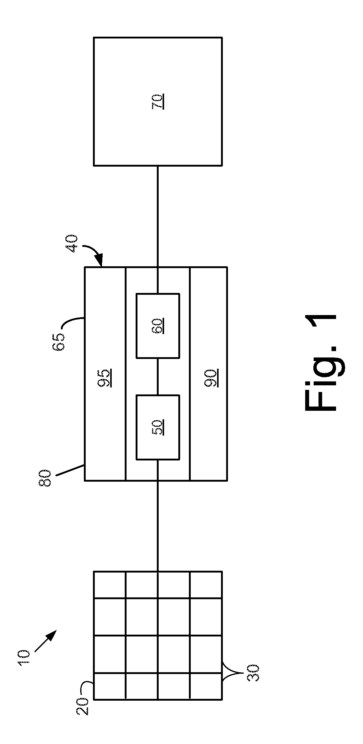
[0013]Referring now to the drawings, in which like numerals refer to like elements through the several views, FIG. 1 shows a known solar power generation system 10. The solar power generation system 10 may include one or more photovoltaic arrays 20. The photovoltaic arrays 20 each may have any number of photovoltaic cells 30 in any desired size and / or configuration. As described above, the photovoltaic cells 30 of the photovoltaic array 20 produce variable DC power based upon the local weather and other operating conditions.

[0014]The solar power generation system 10 further includes a power conversion system 40. The power conversion system 40 includes the components required to convert the DC power from the photovoltaic array 20 to AC power. In this example, the power conversion system 40 may include a DC to DC converter 50. The DC to DC converter 50 may be coupled to the photovoltaic array 20 so as to condition the DC power. The DC to DC converter 50 may include a switching type re...


PUM


Abstract

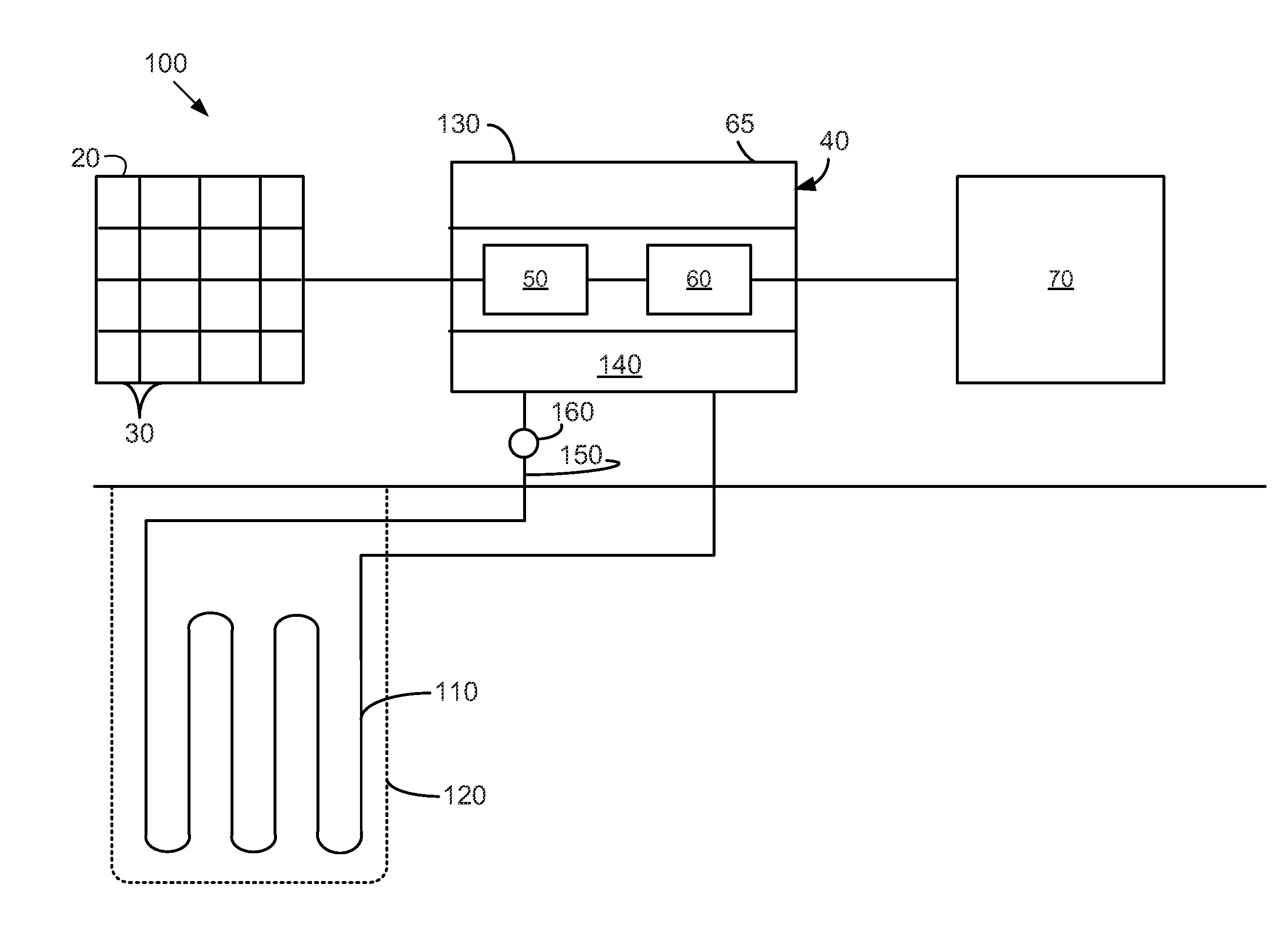
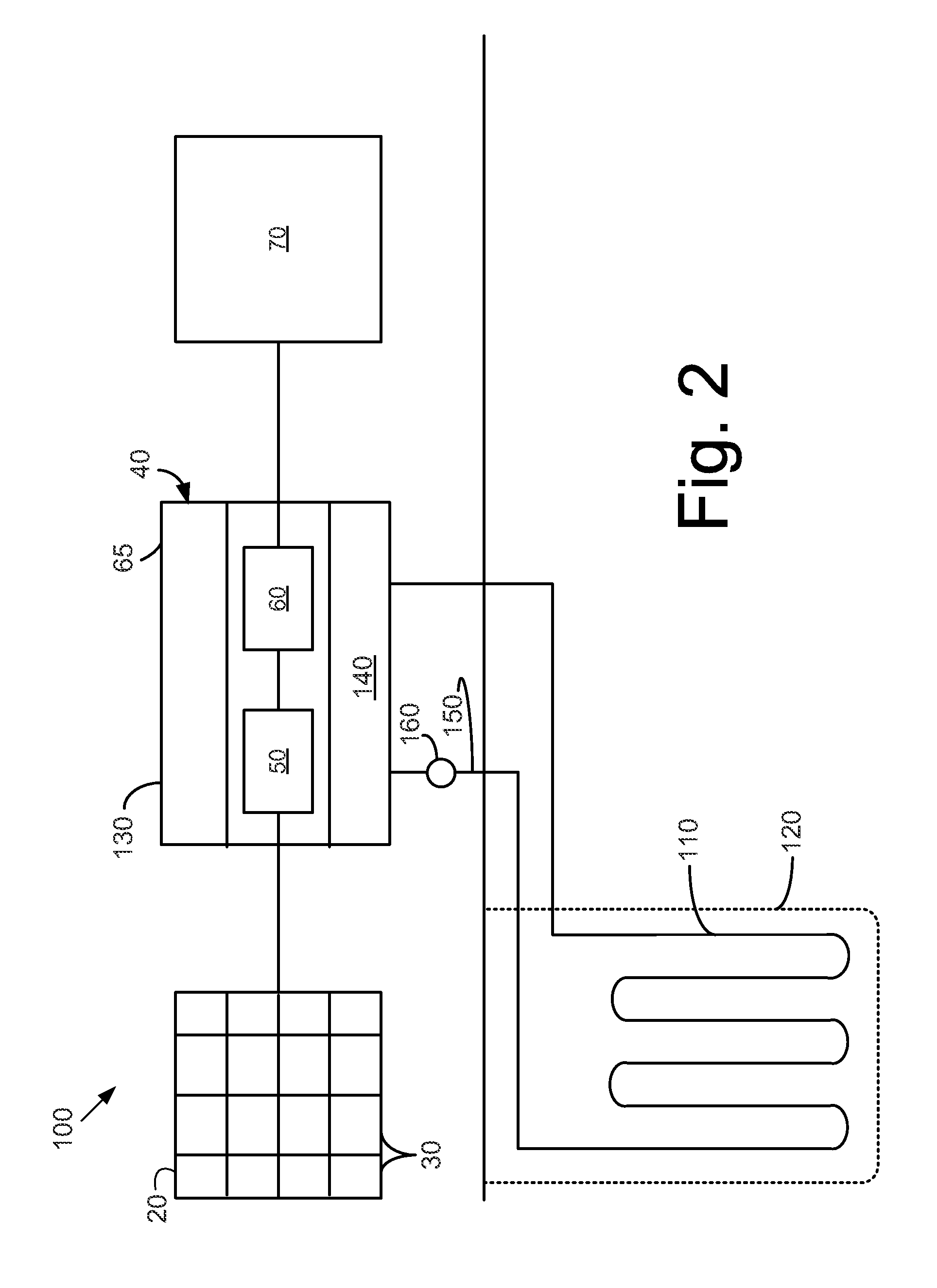
The present application provides a geothermal heating and cooling system for a power conversion system within an enclosure. The geothermal heating and cooling system may include a heat exchanger positioned about the power conversion system and within the enclosure, one or more pipes positioned within the ground, and a heat transfer medium circulating within the heat exchanger and the pipes so as to transfer heat between the power conversion system and the ground.

Description

TECHNICAL FIELD[0001]The present application relates generally to the thermal management of outdoor power conversion equipment and related components and more particularly relates to the use of a geothermal cooling and heating system with a solar power conversion system.BACKGROUND OF THE INVENTION[0002]Power conversion equipment installed and positioned about generating devices has become more and more widespread. Examples include solar power converters and utility grade transmission systems. Power conversion equipment may be used to convert power from a direct current (“DC”) power source, such as from a fuel cell or a photovoltaic cell, to a utility grid. Power conversion equipment installed outdoors also may be used to stabilize alternating current (“AC”) transmission systems by providing real or reactive power, as well as converting AC power into DC power and vice versa for power transmission purposes. Power conversion systems also may be installed in adverse outdoor conditions s...

Claims


Application Information

Patent Timeline
Patent Type & Authority Applications(United States)
IPC IPC(8): H01L31/052F24J3/08F24S10/70
CPCF24J3/08F28D20/0052Y02E10/60Y02E60/142Y02E70/30H02S40/44H02M7/003H02J3/382Y02E10/12H02J3/383Y02E10/563F24J3/081F24T10/10H02J2300/40H02J2300/20H02J2300/24H02J3/381Y02E10/10Y02E10/56Y02E60/14
Inventor TEICHMANN, RALPHALTENSCHULTE, MARKUS
Owner GENERAL ELECTRIC CO
Learn More