
Space frame hub joint

a hub joint and space frame technology, applied in the direction of rod connections, couplings, building repairs, etc., can solve the problems of high cost of conventional hub joints, significant time-consuming and labor-intensive assembling or disassembling, and custom-made components and special tooling

Inactive Publication Date: 2010-06-10
ATHAN STEPHAN P
View PDF62 Cites 15 Cited by
  • Summary
  • Abstract
  • Description
  • Claims
  • Application Information

AI Technical Summary

Benefits of technology

The present invention provides a joint for attaching multiple longitudinal members. The joint includes a rod curved to form a ring or a polygon, longitudinal bores in each member, slots in each member, and clamps for locking the rod. The joint allows for easy assembly and rotation of the longitudinal members. The invention also provides a space frame structure formed by multiple longitudinal members, rods, and clasps. The method of forming the space frame structure includes steps of forming transverse slots at each end of each member, inserting a rod into the slots, and clamping the rod to form hinges. The hinges allow for rotation of the longitudinal members. The invention provides a simple and efficient solution for attaching multiple longitudinal members.

Problems solved by technology

Hub joints used for joining space frames typically include multiple assembly parts, and require significant time to assemble or disassemble using special tools.
The cost of conventional hub joints is typically high, due to components requiring machining or custom fabrication.
A disadvantage of the Leung invention is that it requires custom manufactured components and special tooling.
Furthermore, although the end grips snap into place, they are not locked and, hence, may unexpectedly be unsnapped.
However, the Grimm invention requires custom manufactured components and special tooling, including multiple bolts and pins that have high non-recurring setup and manufacturing costs.
Hence, the cost of manufacturing, assembling, reconfiguring, and disassembling the aforementioned systems is high, when used in large or complex structures.
Furthermore, they may only be used in specific structures for which they were originally intended.
Joints and members cannot be removed after a structure is partially or fully assembled.

Method used


Image

  • Space frame hub joint
  • Space frame hub joint
  • Space frame hub joint

Examples


Embodiment Construction

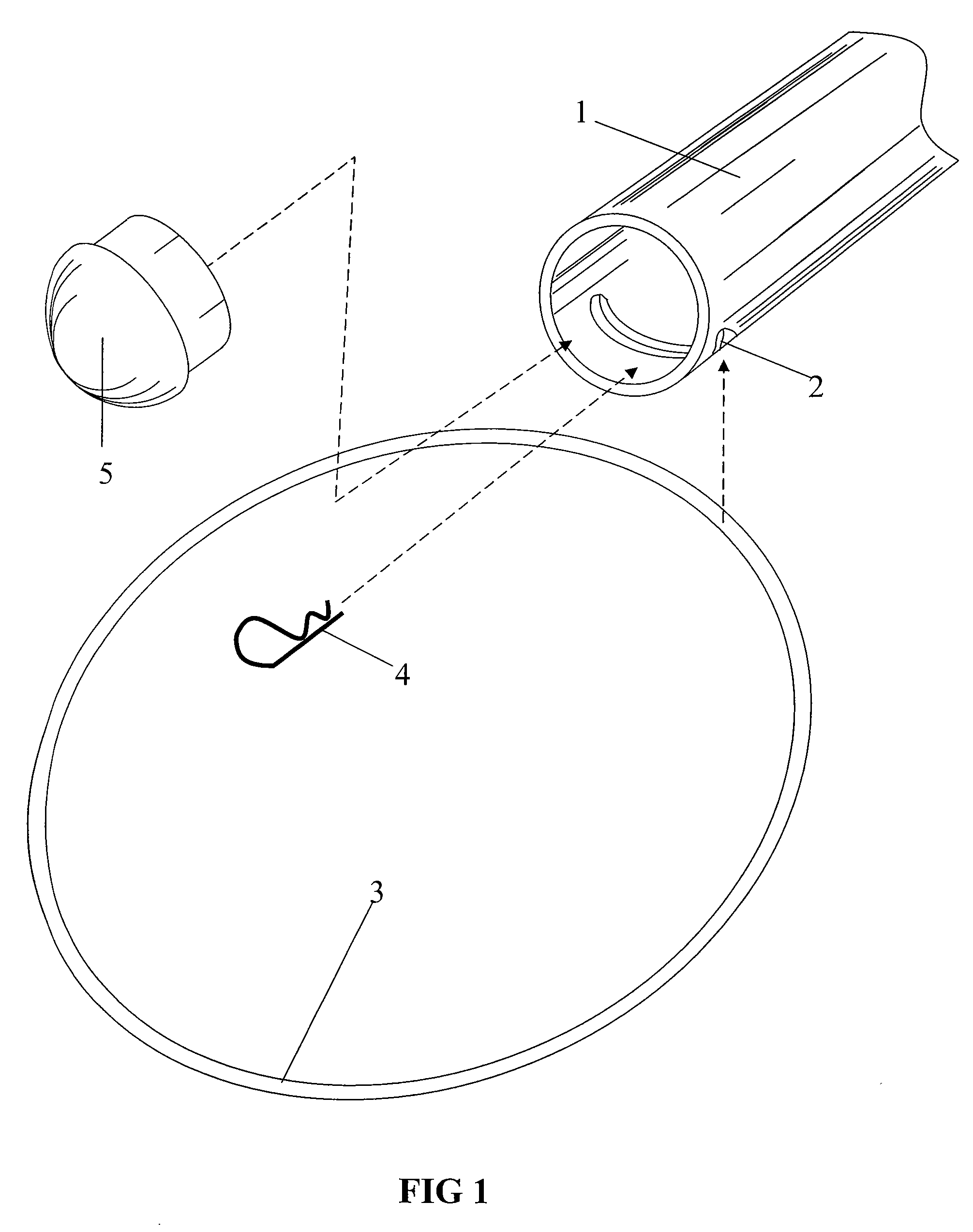
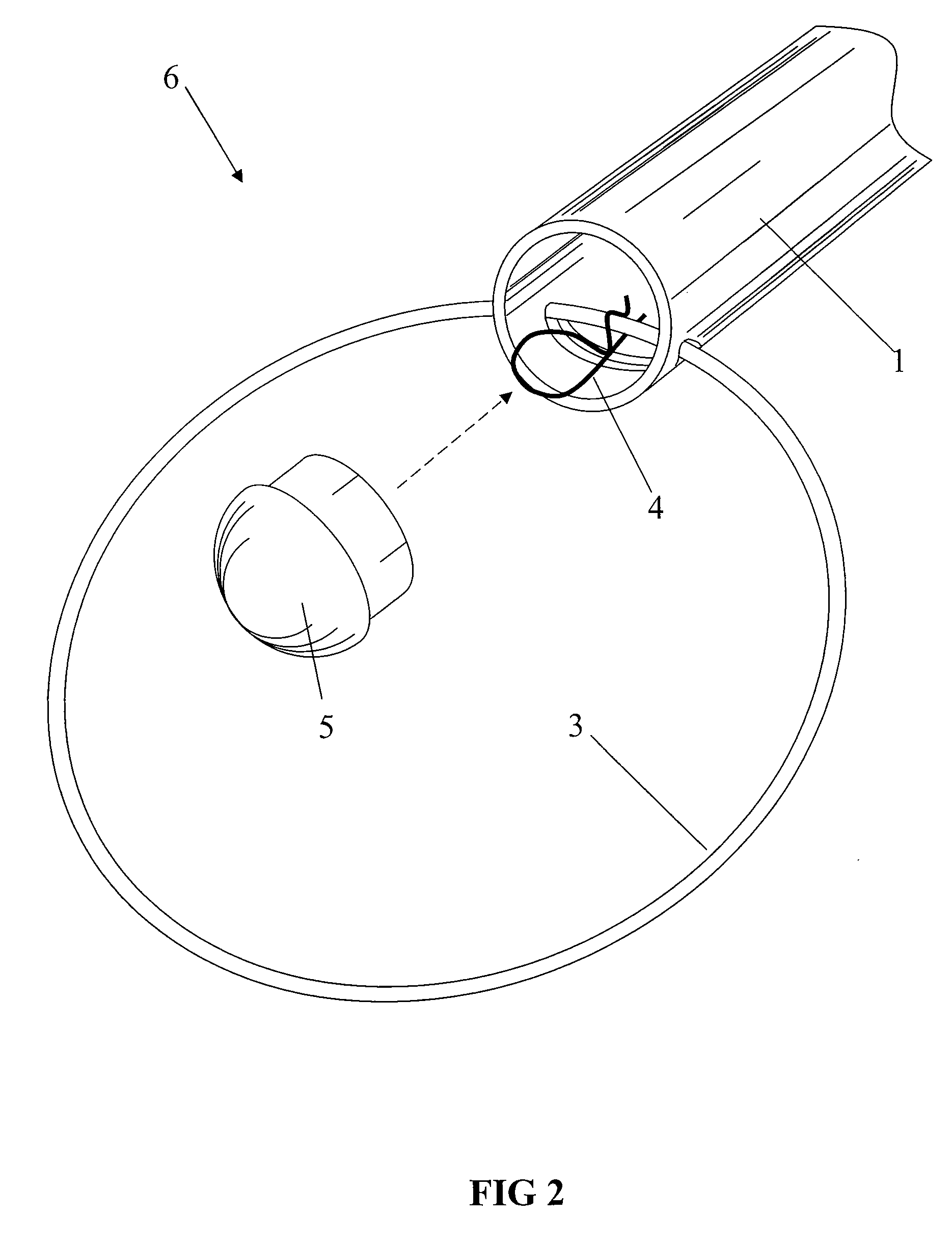
[0080]FIG. 1 shows a longitudinal tubular member 1, with a transverse slot or notch 2, cut through a circumferential wall of the member, which is adjacent to the end of the member. The figure also shows ring 3, pin 4, and end cap 5. The components in FIG. 1 are assembled by inserting ring 3 into slot 2. The pin 4 is then inserted through the open end of the tubular member for enveloping the ring segment inserted through notch 2. The pin 4 thus prevents the ring from falling out of the notch. End cap 5 is fitted into the end of the tubular member, after the pin is inserted. This provides a covering for the open end of the member. The end cap 5 is shown inserted into the tube end; however, an outside end cap may be used with a slightly larger end cap and ring diameter.

[0081]The notch 2 may be formed at one end or both ends of the tubular member, for example, one half inch from each end. The tubular member 1 is free to pivot almost 360 degrees about its ring segment while still retaini...


PUM


Abstract

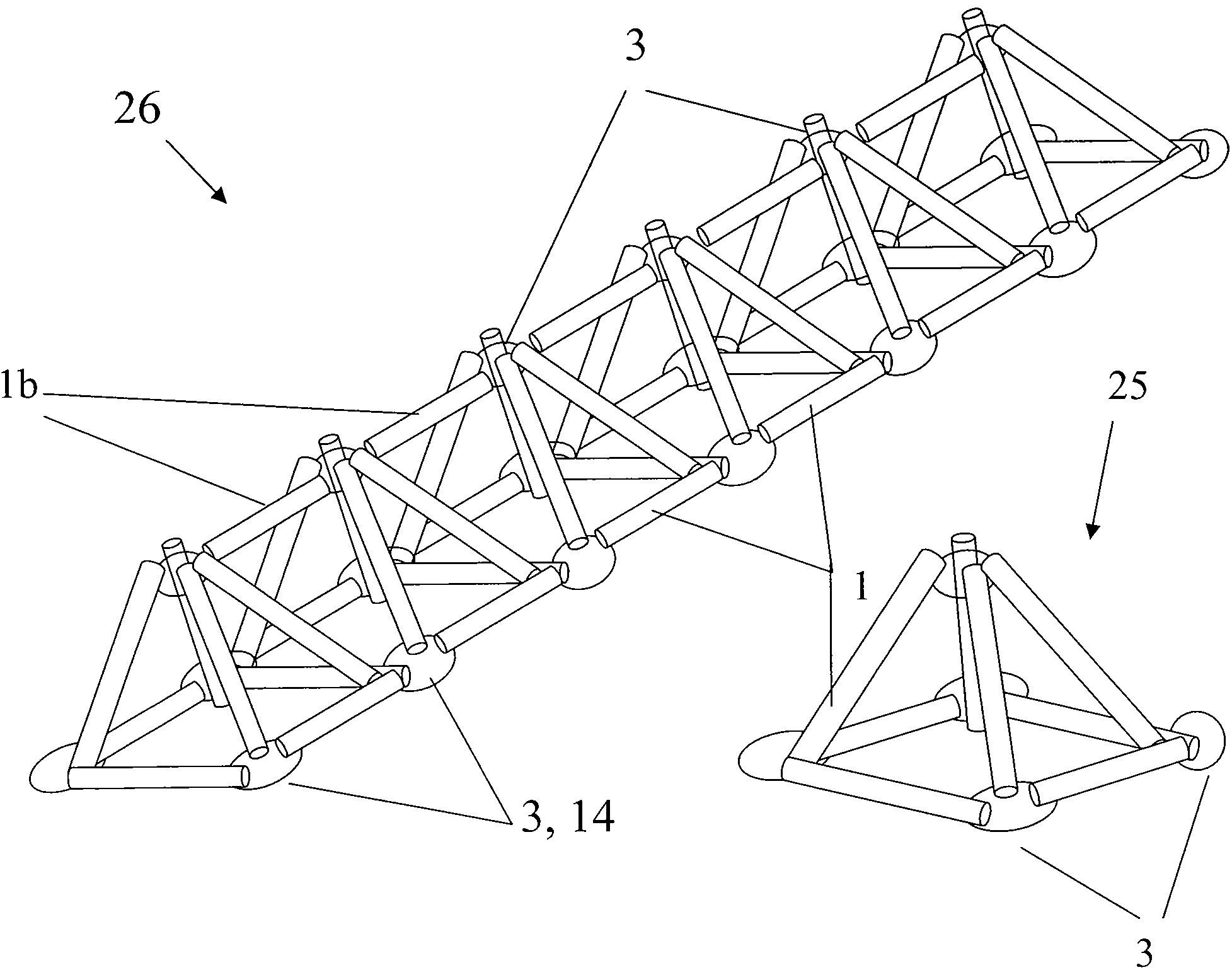
A hub joint includes a metal rod and pin for joining tubular members in three-dimensional space for assembling a frame structure. The hub joint enables rapid assembly, rapid reconfiguration, and rapid disassembly without using any specialized tools. Multiple hub joints may be used to form geodesic domes, freestanding trusses, space frame slabs, tetrahedrons, and pentahedrons. The hub joints allow different frame configurations that are lightweight, strong, durable, scalable, expandable, and portable.

Description

BACKGROUND OF THE INVENTION[0001]Hub joints used for joining space frames typically include multiple assembly parts, and require significant time to assemble or disassemble using special tools. Conventional hub joints may only be assembled into a specific structure. The cost of conventional hub joints is typically high, due to components requiring machining or custom fabrication.[0002]Space frames have increased in popularity in the last decades. This is due to better materials and computer aided design tools. Indeed, complex space frame and truss structures may be seen in many applications including amusement parks, commercial buildings, complexes, hangers, space stations, playgrounds, road signs, towers, and tents, for example.[0003]A key component of any space frame structure is the connector or joint. The type of joint depends on the connection method (welding, bolting, etc.), the size of the joining members, and the role the space frame has in the application. Many types of joi...

Claims


Application Information

Patent Timeline
Patent Type & Authority Applications(United States)
IPC IPC(8): F16B7/00E04H12/00E04B1/19
CPCE04B1/19E04B1/1903E04B1/3211E04B2001/0053E04B2001/1927Y10T403/32581E04B2001/199E04B2001/1993E04B2001/3247F16B7/0446Y10T403/34E04B2001/1987
Inventor ATHAN, STEPHAN P.
Owner ATHAN STEPHAN P
Learn More