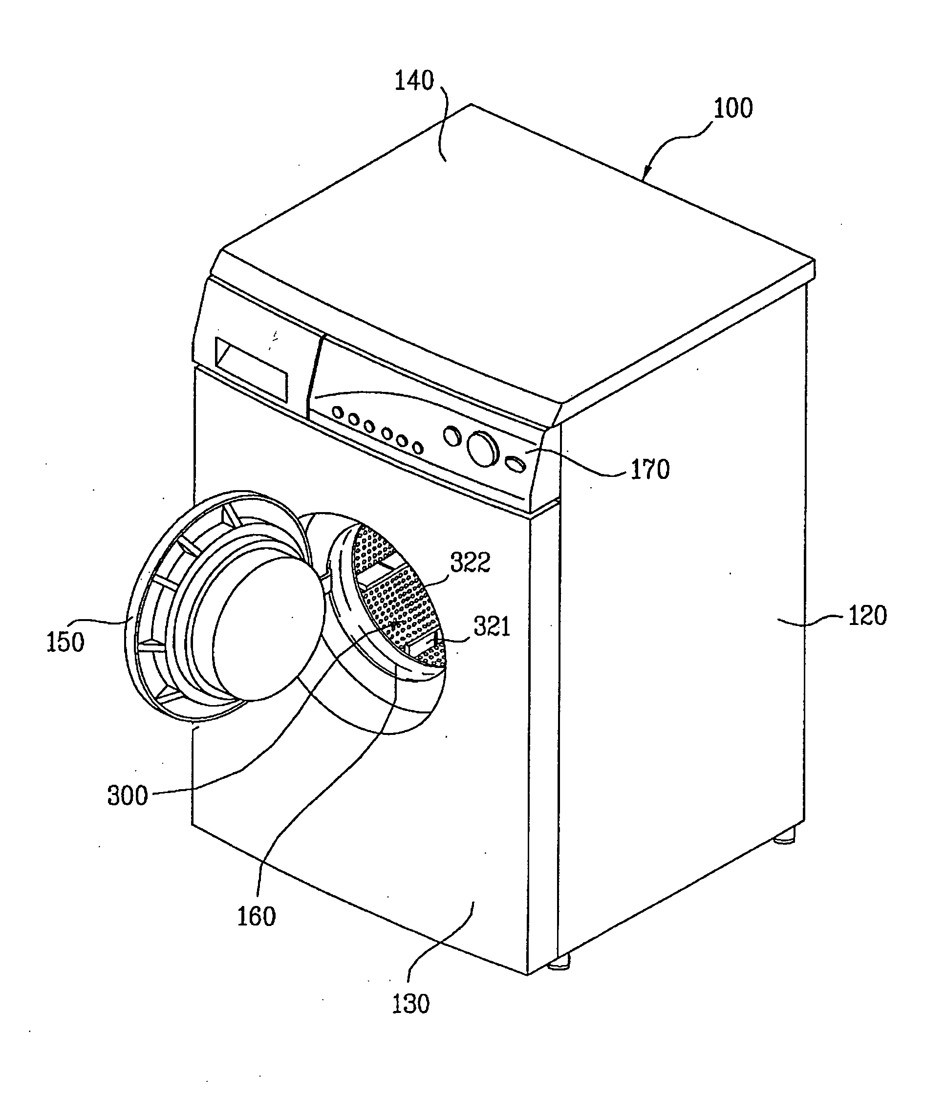
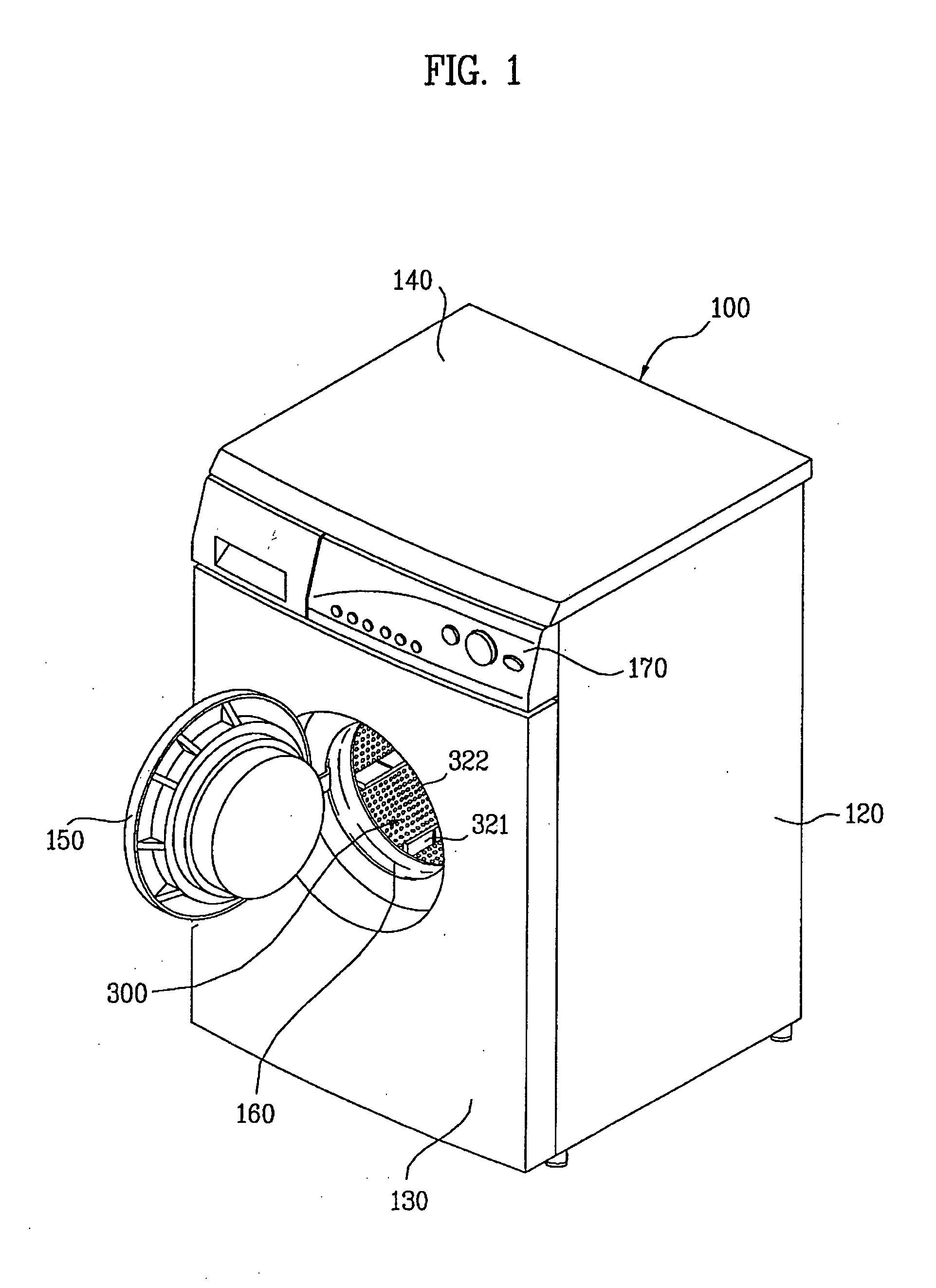
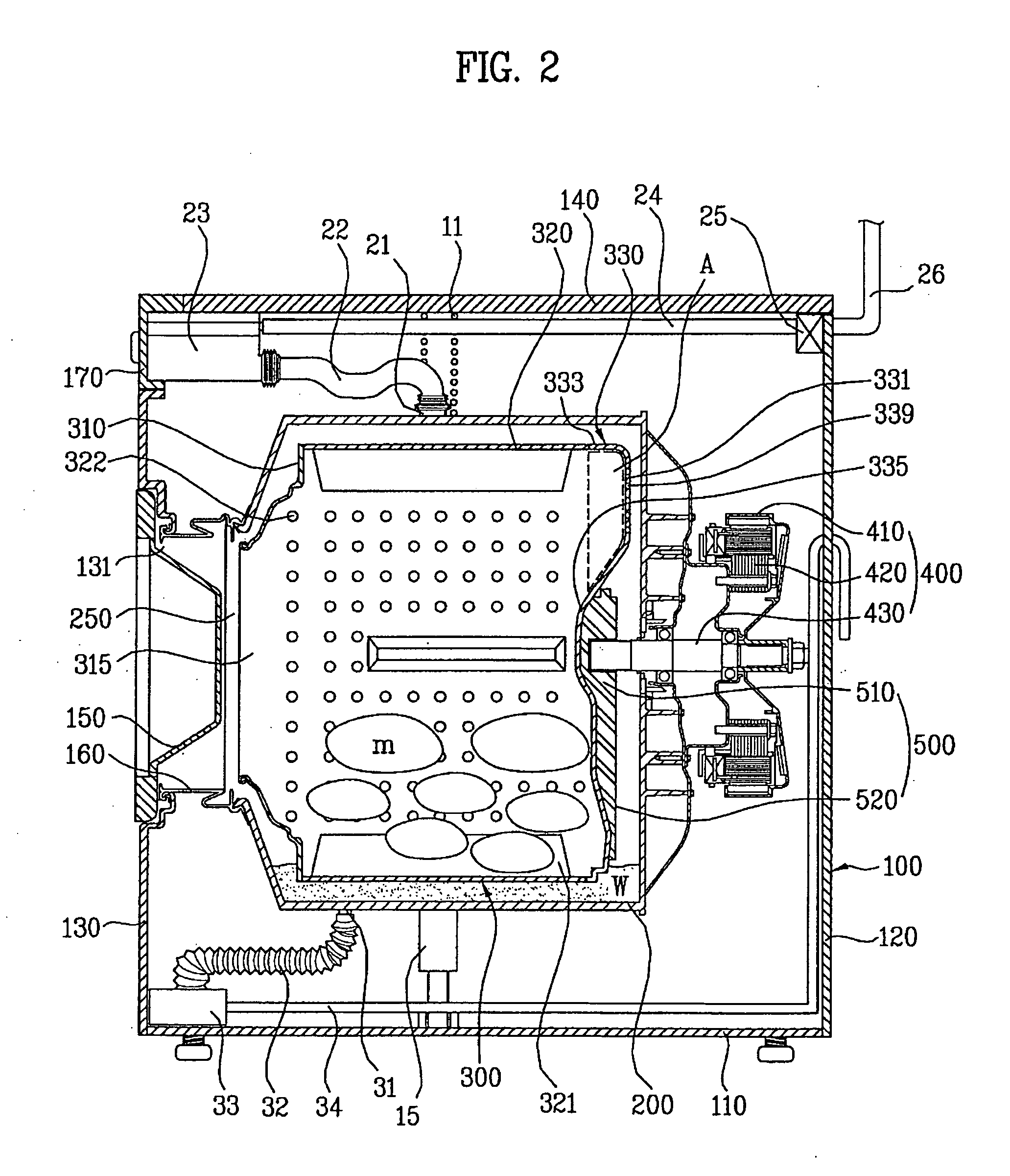
Drum assembly in washing machine and method for fabricating the same
a drum and washing machine technology, applied in the field of drum assembly, can solve the problems of significant increase in production cost, and achieve the effects of enhancing and improving bottom stiffness and strength
- Summary
- Abstract
- Description
- Claims
- Application Information
AI Technical Summary
Benefits of technology
Problems solved by technology
Method used
Image

Examples
second embodiment
[0050]Referring to FIGS. 6 and 7, it can be noted that a structure of the bottom of the drum in accordance with a second preferred embodiment of the present invention is similar to the structure of the bottom of the drum in accordance with the first preferred embodiment of the present invention, except that the bottom 330 of the second embodiment has a reinforcing rib 337a provided additionally for reinforcing the bottom 330, which will be described hereafter.
[0051]Referring to FIGS. 6 and 7, the expansion region 331 of the bottom 330 is provided with a reinforcing rib 337a, projected toward an inside of the drum from the flat portion 336 of the expansion region 331, for enhancing stiffness and strength of the bottom 330. As shown in FIGS. 6 and 7, the reinforcing rib 337a is provided to each of the expansion regions 331, and an arc concentric with the bottom 330 having a curvature the same with the rim 333 of the bottom 330. As shown in FIG. 7, the reinforcing rib 337a is formed as...
third embodiment
[0055]Referring to FIGS. 10 and 11, the expansion region 331 of the bottom of the drum in accordance with a fourth preferred embodiment of the present invention is provided, not only with the reinforcing rib 337b, but also with a stepped portion 338. Since the reinforcing rib 337b has a structure the same with the third embodiment, the stepped portion 338 will be described hereafter. The stepped portion 338 is provided to the expansion region 331, for enhancing stiffness and strength of the bottom 330. As shown in FIGS. 10 and 11, the stepped portion is formed to be concentric with the rim 320 of the drum 300. In other words, a center of curvature of the stepped portion 338 is the axis of the drum 300. The stepped portion 338 is parallel to the axis of the drum 300. Of course, the structure of the stepped portion 338 is not limited to above, but may be formed sloped to the axis.
[0056]As described before, if the stepped portion 338 is provided to the bottom 330, as shown in FIG. 11, ...
fourth embodiment
[0058]Referring to above drawings, the expansion region 331 of the bottom of the drum in accordance with a fifth preferred embodiment of the present invention is provided with a stepped portion 338, and protruded portions 337c. The stepped portion has a structure similar to the However, as shown in FIG. 13, the stepped portion 338 may be sloped with reference to the axis of the drum 300. Of course, the structure of the stepped portion is not limited to this, but the stepped portion may be formed parallel to the axis. The protruded portion 337c, protruded from the stepped portion 338 toward a radial direction of the bottom 330, enhances stiffness and strength of the bottom 330. For an example, as shown in FIG. 12, the protruded portion 337c is protruded from the stepped portion 338 toward the axis of the drum 300. However, the structure of the protruded portion 337c is not limited to this, but the protruded portion 337c may be protruded in a direction opposite to above.
[0059]In the ...
PUM
| Property | Measurement | Unit |
|---|---|---|
| circumference | aaaaa | aaaaa |
| stiffness | aaaaa | aaaaa |
| strength | aaaaa | aaaaa |
Abstract
Description
Claims
Application Information
 - R&D
- Intellectual Property
- Life Sciences
- Materials
- Tech Scout
- Unparalleled Data Quality
- Higher Quality Content
- 60% Fewer Hallucinations
Browse by: Latest US Patents, China's latest patents, Technical Efficacy Thesaurus, Application Domain, Technology Topic, Popular Technical Reports.
© 2025 PatSnap. All rights reserved.Legal|Privacy policy|Modern Slavery Act Transparency Statement|Sitemap|About US| Contact US: help@patsnap.com