Coding Apparatus and Decoding Apparatus
a technology which is applied in the field of decoding apparatus and coding apparatus, can solve the problems of lack of realism, insufficient, and muffled sound, and achieve the effects of improving sound quality, low bit rate, and high quality
- Summary
- Abstract
- Description
- Claims
- Application Information
AI Technical Summary
Benefits of technology
Problems solved by technology
Method used
Image
Examples
embodiment 1
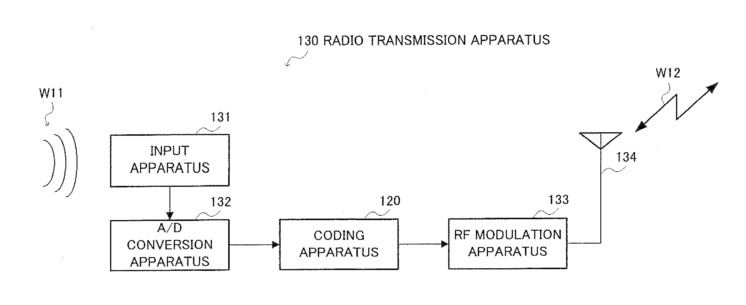
[0045]FIG. 3 is a block diagram showing the principal configuration of radio transmission apparatus 130 when a radio coding apparatus according to Embodiment 1 of the present invention is mounted on the transmitting side of a radio communication system.
[0046]This radio transmission apparatus 130 includes coding apparatus 120, input apparatus 131, A / D conversion apparatus 132, RF modulation apparatus 133 and antenna 134.
[0047]Input apparatus 131 converts sound wave W11 audible to human ears to an analog signal which is an electric signal and outputs the signal to A / D conversion apparatus 132. A / D conversion apparatus 132 converts this analog signal to a digital signal and outputs the digital signal to coding apparatus 120. Coding apparatus 120 encodes the input digital signal, generates a coded signal and outputs the coded signal to RF modulation apparatus 133. RF modulation apparatus 133 modulates the coded signal, generates a modulated coded signal and outputs the modulated coded s...
embodiment 2
[0117]FIG. 15 is a block diagram showing the principal configuration of spectrum coding section 200 in a coding apparatus according to Embodiment 2 of the present invention. This spectrum coding section 200 has a basic configuration similar to that of spectrum coding section 100 shown in FIG. 5 and the same components are assigned the same reference numerals and explanations thereof will be omitted.
[0118]A feature of this embodiment is to make a filter function used in the filtering section simpler than that in Embodiment 1.
[0119]For the filter function used in filtering section 201, a simplified one as shown in the following equation is used.
P(z)=11-z-T(Equation5)
[0120]This equation corresponds to a filter function assuming M=0, (β0=1 in (Equation 1).
[0121]FIG. 16 illustrates an overview of filtering using the above described filter.
[0122]Estimated value S′2(k) of a second spectrum is obtained by sequentially copying low-frequency spectra separated by T. Furthermore, search section...
embodiment 3
[0127]FIG. 17 is a block diagram showing the principal configuration of spectrum coding section 300 in a coding apparatus according to Embodiment 3 of the present invention. This spectrum coding section 300 has a basic configuration similar to that of spectrum coding section 100 shown in FIG. 5 and the same components are assigned the same reference numerals and explanations thereof will be omitted.
[0128]A feature of this embodiment is to further comprise outline calculation section 301 and multiplexing section 302 and perform coding of envelope information about a second spectrum after estimating the second spectrum.
[0129]Search section 108 outputs optimum pitch coefficient T′ to multiplexing section 302 and outputs estimated value S′2(k) of the second spectrum generated using this pitch coefficient T′ to outline calculation section 301. Outline calculation section 301 calculates envelope information about second spectrum S2(k) based on second spectrum S2(k) provided from frequency...
PUM
 Abstract
Description
Claims
Application Information
 - R&D
- Intellectual Property
- Life Sciences
- Materials
- Tech Scout
- Unparalleled Data Quality
- Higher Quality Content
- 60% Fewer Hallucinations
Browse by: Latest US Patents, China's latest patents, Technical Efficacy Thesaurus, Application Domain, Technology Topic, Popular Technical Reports.
© 2025 PatSnap. All rights reserved.Legal|Privacy policy|Modern Slavery Act Transparency Statement|Sitemap|About US| Contact US: help@patsnap.com


