
Sphygmomanometer cuff and sphygmomanometer

Inactive Publication Date: 2010-06-03
OMRON HEALTHCARE CO LTD
View PDF19 Cites 27 Cited by
  • Summary
  • Abstract
  • Description
  • Claims
  • Application Information

AI Technical Summary

Benefits of technology

[0034]According to the present invention, the internal bleeding that may occur when measuring the blood pressure is reliably prevented.

Problems solved by technology

The sphygmomanometer cuff described above has a problem that wrinkles form at the compression acting surface of the fluid bag when measuring the blood pressure.
If wrinkles are formed at the compression acting surface of the fluid bag, part of the measuring site may be trapped in the valley portions of the wrinkles, which may cause slight internal bleeding at the measuring site.
As a result, slight internal bleeding may occur at the relevant portion when measuring the blood pressure.
The wrinkles formed at the compression acting surface of the air bladder thus become the cause of slight internal bleeding at the measuring site of a subject.

Method used


Image

  • Sphygmomanometer cuff and sphygmomanometer
  • Sphygmomanometer cuff and sphygmomanometer
  • Sphygmomanometer cuff and sphygmomanometer

Examples


first embodiment

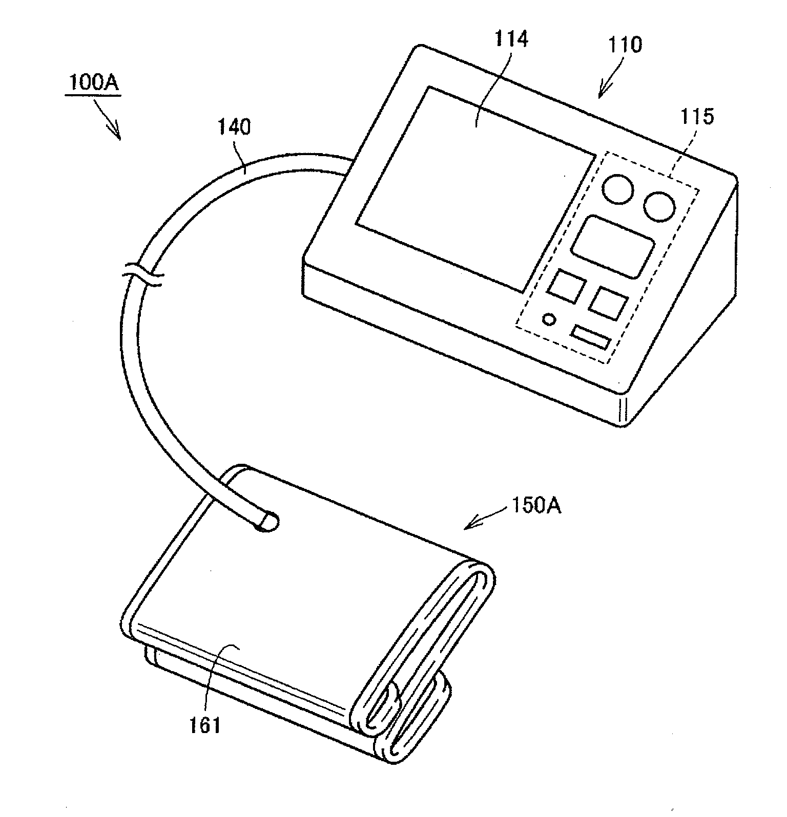
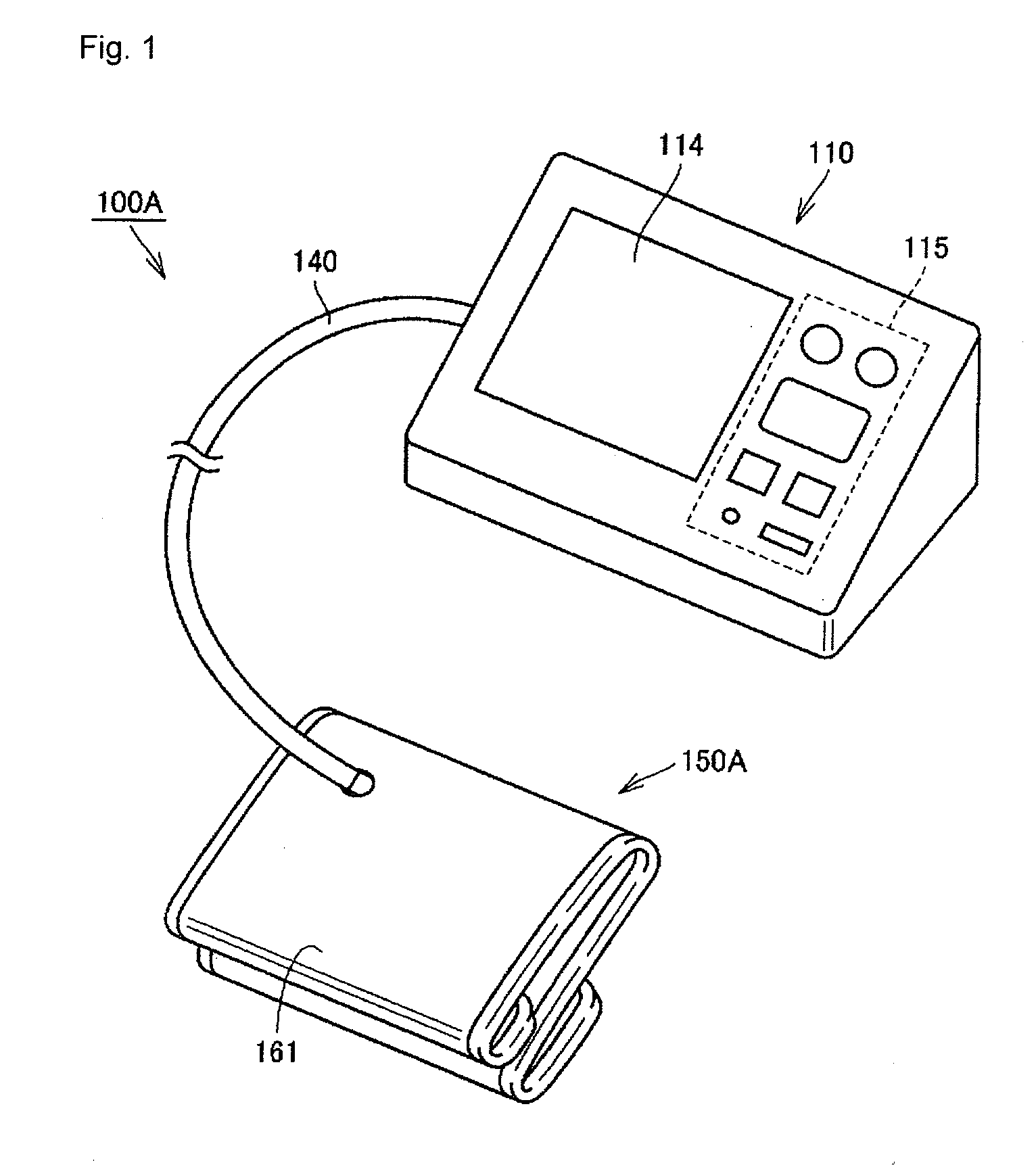
[0067]FIG. 1 is a perspective view showing an outer appearance of a sphygmomanometer according to a first embodiment of the present invention. First, the outer appearance structure of the sphygmomanometer according to the present embodiment will be described with reference to FIG. 1.

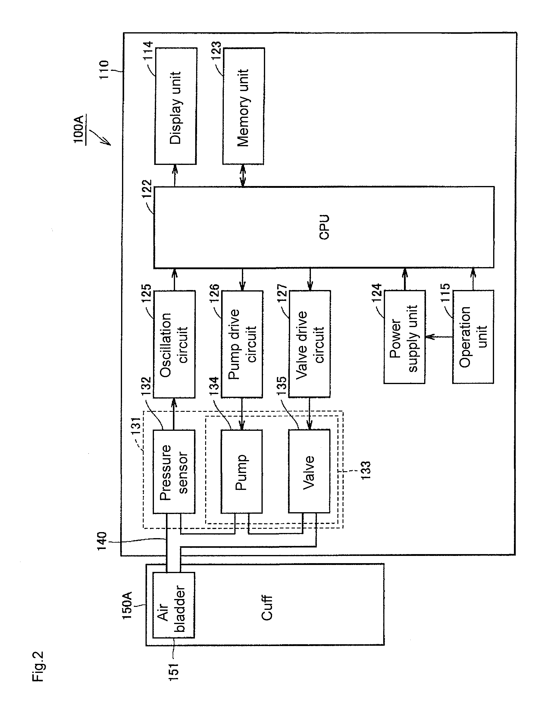
[0068]As shown in FIG. 1, a sphygmomanometer 100A according to the present embodiment mainly includes a device main body 110 and a cuff 150A. The device main body 110 has a display unit 114 and an operation unit 115. The display unit 114 visually displays the measurement result of a blood pressure value, the measurement result of a pulse rate, and the like using numerical values and graphs. A liquid crystal panel, or the like is used for the display unit 114. The operation unit 115 is arranged with a power button, a measurement start button, and the like.

[0069]The cuff 150A is intended to be wrapped around the upper arm of the left arm or the upper arm of the right arm of a subject, and has a band-shaped...

second embodiment

[0112]FIGS. 16 and 17 are perspective views showing an outer appearance structure of a sphygmomanometer according to a second embodiment of the present invention. FIGS. 18 and 19 are cross-sectional views of a sphygmomanometer cuff according to the present embodiment. The cross-section of the sphygmomanometer cuff shown in FIG. 19 is a cross-sectional view taken along line XIX-XIX shown in FIG. 18. The function blocks and the measurement flow of the sphygmomanometer 100B according to the present embodiment conform to those of the sphygmomanometer 100A according to the first embodiment, and thus the description thereof will not be repeated.

[0113]First, the outer appearance structure of the sphygmomanometer according to the present embodiment will be described with reference to FIGS. 16 and 17. As shown in FIGS. 16 and 17, the sphygmomanometer 1008 according to the present embodiment mainly includes the device main body 110 mounted on a mounting surface of a desk, or the like, and a c...


PUM


Abstract

A sphygmomanometer cuff is used by being wrapped around an upper arm, and includes an air bladder, a cover body, and a cushion material. The air bladder is inflated / contracted by in / out of fluid, and includes a compression acting surface positioned on the upper arm side when the sphygmomanometer cuff is wrapped around the upper arm. The cover body internally includes the air bladder, and includes an inner peripheral side sheet portion positioned on the upper arm side when the sphygmomanometer cuff is wrapped around the upper arm. The cushion material is positioned on the inner peripheral side sheet portion side than the compression acting surface, and is compressible in a direction parallel to a thickness direction of the inner peripheral side sheet portion. According to such a configuration, the internal bleeding at the measuring site that may occur when measuring the blood pressure is reliably prevented.

Description

CROSS REFERENCE TO RELATED APPLICATIONS[0001]This application is a National Stage application of PCT / JP2007 / 068975, filed Sep. 28, 2007, which claims the benefit of priority of Japanese Application No. 2006-274223, filed Oct. 5, 2006, the entire contents of these applications hereby incorporated by reference.TECHNICAL FIELD[0002]The present invention relates to a sphygmomanometer cuff used by being wrapped around a measuring site of a living body such as a wrist or an upper arm when measuring blood pressure, and a sphygmomanometer equipped with the same.BACKGROUND ART[0003]Normally, when measuring a blood pressure value, a cuff internally including a fluid bag for putting pressure on an artery in a living body is wrapped around the body surface of the living body, and the wrapped fluid bag is inflated and contracted to detect the arterial pressure pulse wave generated in the artery to thereby measure the blood pressure value. Here, the cuff refers to a band-shaped structural body ha...

Claims


Application Information

Patent Timeline
IPC IPC(8): A61B5/0225
CPCA61B5/02233
Inventor TAKAHASHI, AKIHISAONISHI, YOSHIHIDEKUKITA, TOMOHIROUESAKA, CHISATOSAWANOI, YUKIYAYANAGASE, MASATAKA
Owner OMRON HEALTHCARE CO LTD
Learn More