System and method for phase load discovery
a technology of system and method, applied in the direction of polyphase network asymmetry measurement, phase sequence/synchronization indication, instruments, etc., can solve the problems of theft of energy, unbalanced actual load on and difficulty in determining the actual load connected to each of the three phases
- Summary
- Abstract
- Description
- Claims
- Application Information
AI Technical Summary
Benefits of technology
Problems solved by technology
Method used
Image

Examples
first embodiment
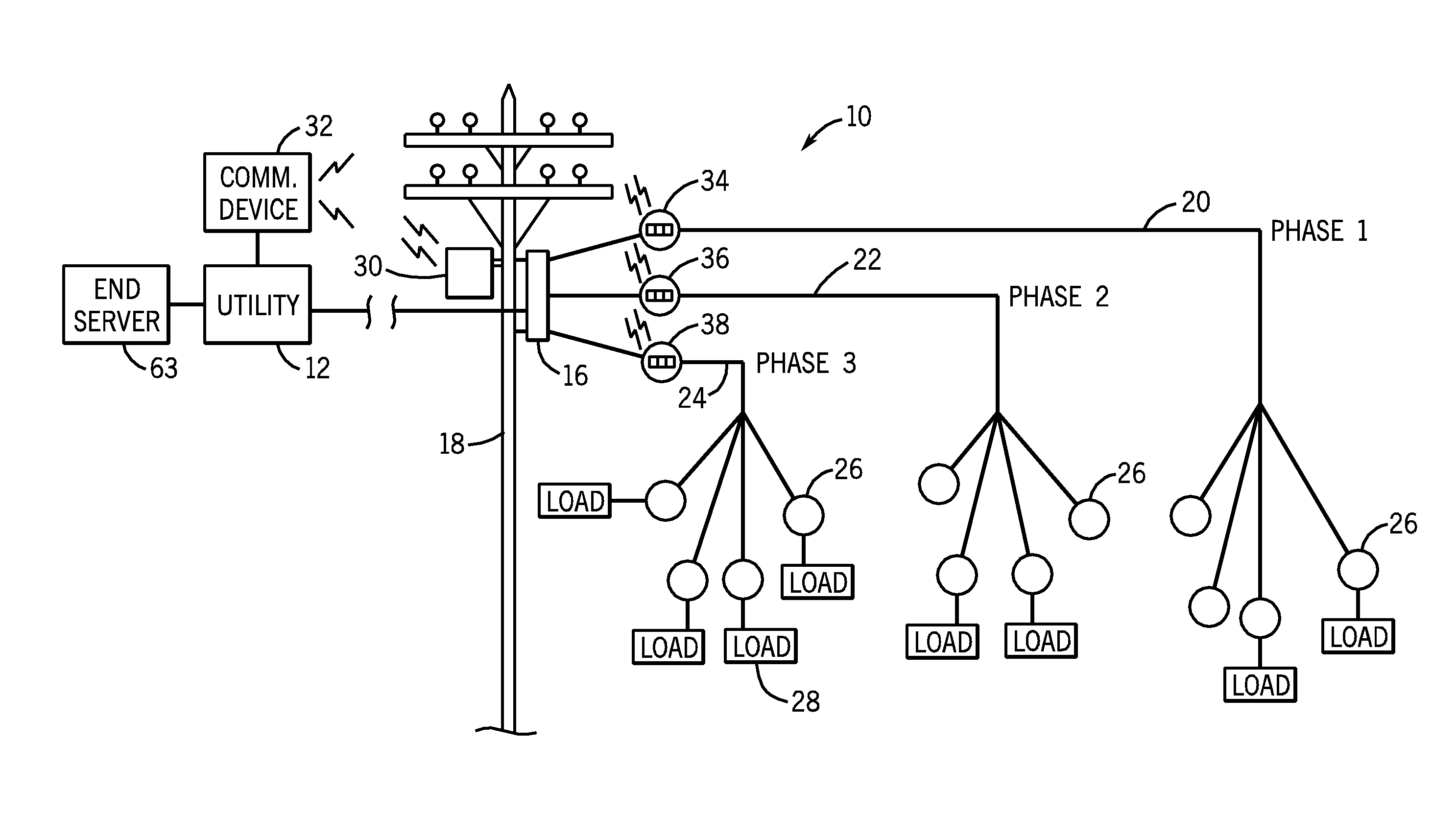
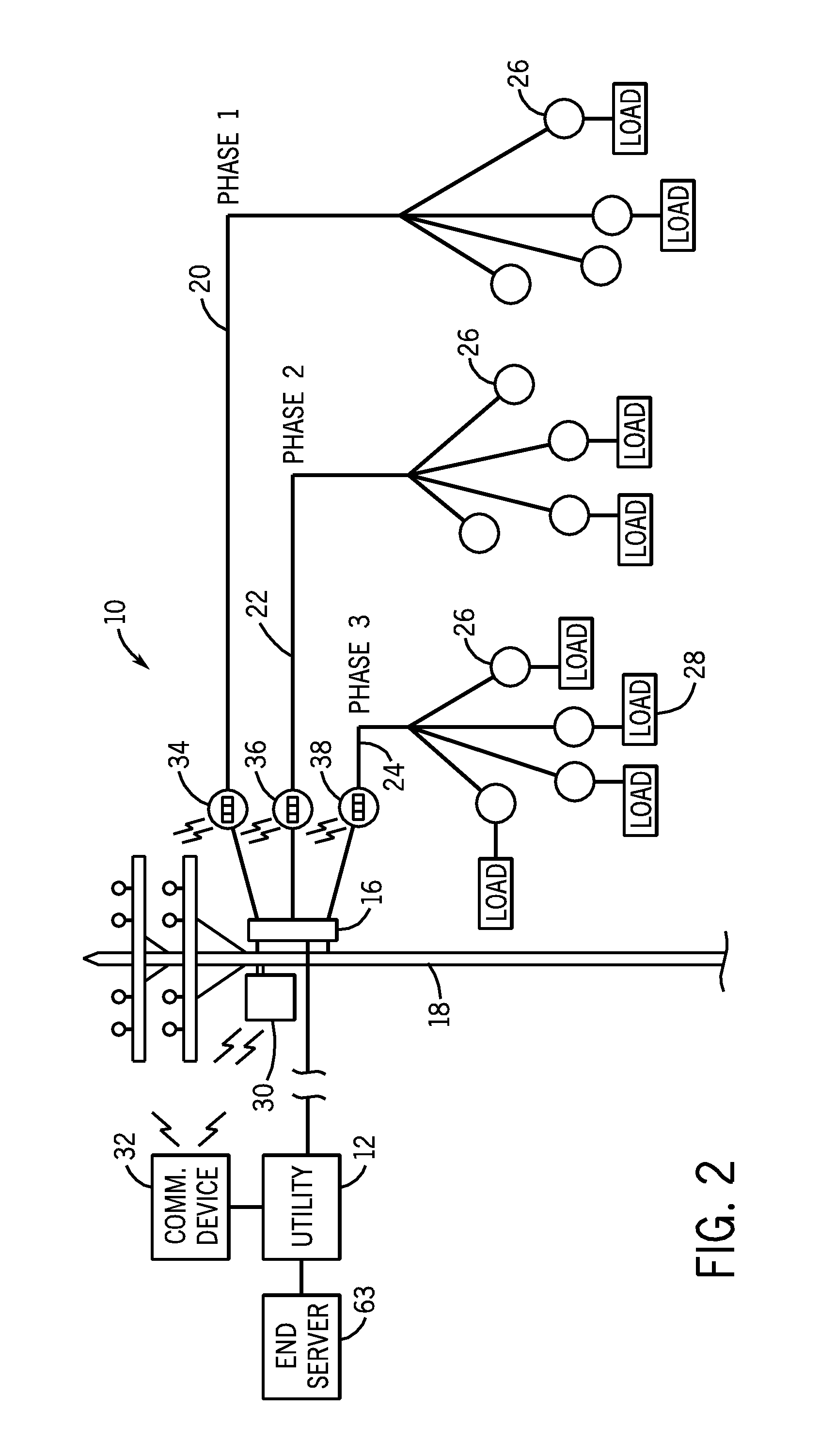
[0027]FIG. 2 illustrates a system for determining which phase each of the load meters 26 are connected to in the energy distribution system 10. The electricity distribution system 10 shown in FIG. 2 is similar to the prior art system shown in FIG. 1 in that the pole mounted transformer 16 distributes the three phases of the electricity over a first phase line 20, a second phase line 22 and a third phase line 24. A plurality of load meters 26 are connected to each of the three supply lines 20, 22 and 24, as in the embodiment shown in FIG. 1.
[0028]In the embodiment shown in FIG. 2, the energy distribution system includes a first feeder meter 34 connected to supply line 20, a second feeder meter 36 connected to the second supply line 22 and a third feeder meter 38 connected to the third supply line 24. As illustrated in FIG. 2, each of the feeder meters 34-36 is positioned to determine the consumption of the combined loads connected to each of the respective supply lines 20, 22 and 24....
second embodiment
[0047]In the present disclosure, the gateway 30 is connected to one of the phases of the electricity supply. The gateway 30 will be configured to include a zero detector that allows the gateway 30 to determine a zero crossing of the phase to which the gateway is connected.
[0048]Referring now to FIG. 5, in the embodiment being described, the gateway 30 is connected to phase 1. In accordance with the second embodiment, the gateway 30 generates the timing pulse 66 at the zero crossing of phase 1. In addition to sending the timing pulse 66, the gateway also sends a message that indicates the number of milliseconds to the next zero crossing. In the embodiment shown in FIG. 5, the time delay from the timing pulse 66 to the next zero crossing is approximately eight milliseconds.
[0049]Once the timing pulse has been sent, each of the individual load meters 26 receives the timing pulse and determines the time delay for the next zero crossing for the individual load meter. In the embodiment sh...
PUM
 Abstract
Description
Claims
Application Information
 - R&D
- Intellectual Property
- Life Sciences
- Materials
- Tech Scout
- Unparalleled Data Quality
- Higher Quality Content
- 60% Fewer Hallucinations
Browse by: Latest US Patents, China's latest patents, Technical Efficacy Thesaurus, Application Domain, Technology Topic, Popular Technical Reports.
© 2025 PatSnap. All rights reserved.Legal|Privacy policy|Modern Slavery Act Transparency Statement|Sitemap|About US| Contact US: help@patsnap.com