
Thyristor controllied series capacitor adapted to damp sub synchronous resonances

a sub-synchronous resonance and capacitor technology, applied in the direction of power oscillation reduction/prevention, ac network circuit arrangement, electrical equipment, etc., can solve the problems of provoking a very high mechanical stress in the shaft, provoking torsional oscillations with very high amplitude, and affecting the control of the power network. , to achieve the effect of reducing the occurrence of sub-synchronous resonances and improving the control of the power network

Inactive Publication Date: 2010-06-03
ABB POWER GRIDS SWITZERLAND AG +1
View PDF17 Cites 7 Cited by
  • Summary
  • Abstract
  • Description
  • Claims
  • Application Information

AI Technical Summary

Benefits of technology

[0016]A primary object of the present invention is to seek ways to improve the control of a power network to mitigate the occurrence of subsynchronous resonances (SSR) that could harm the mechanic or the electric equipment.
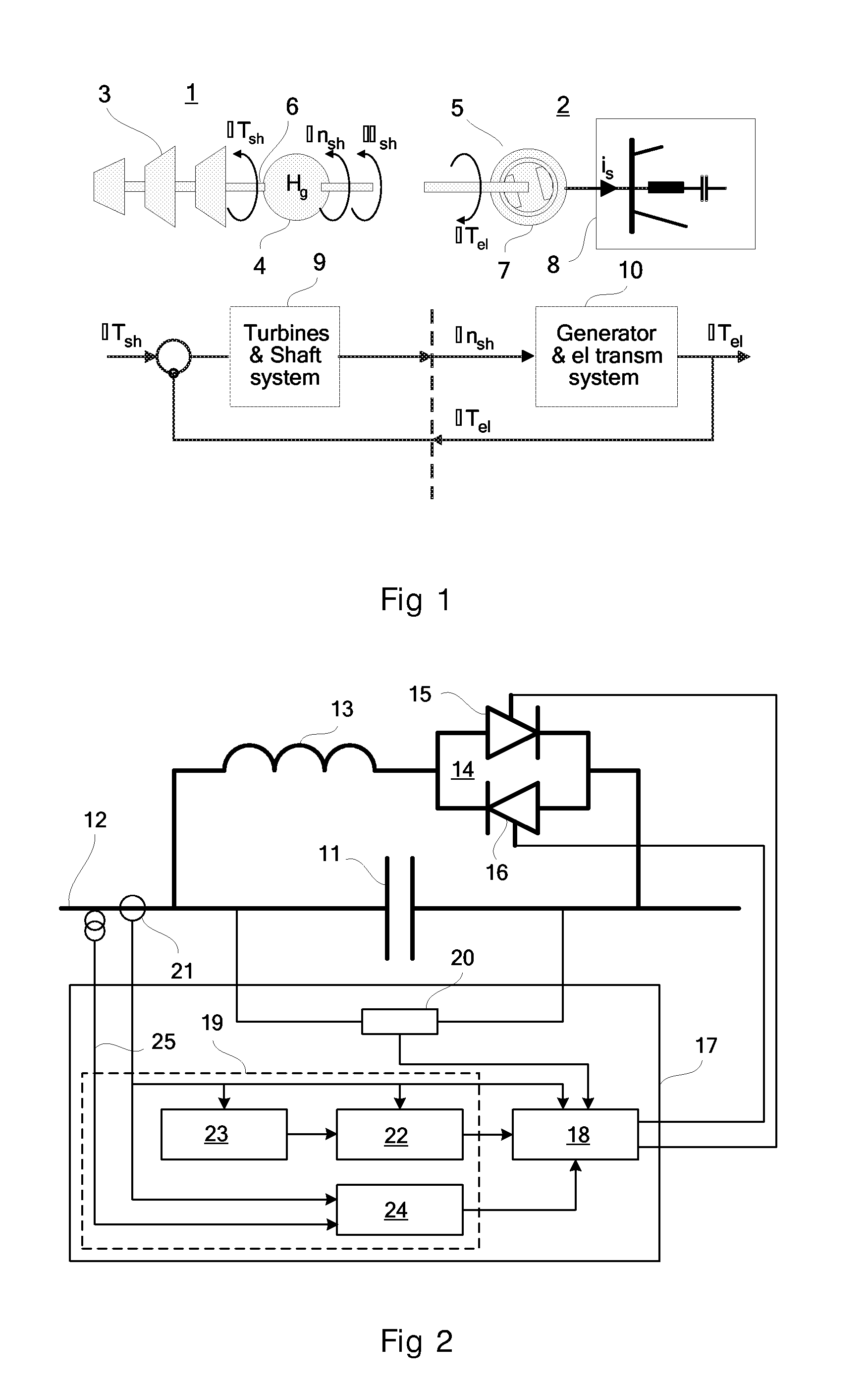
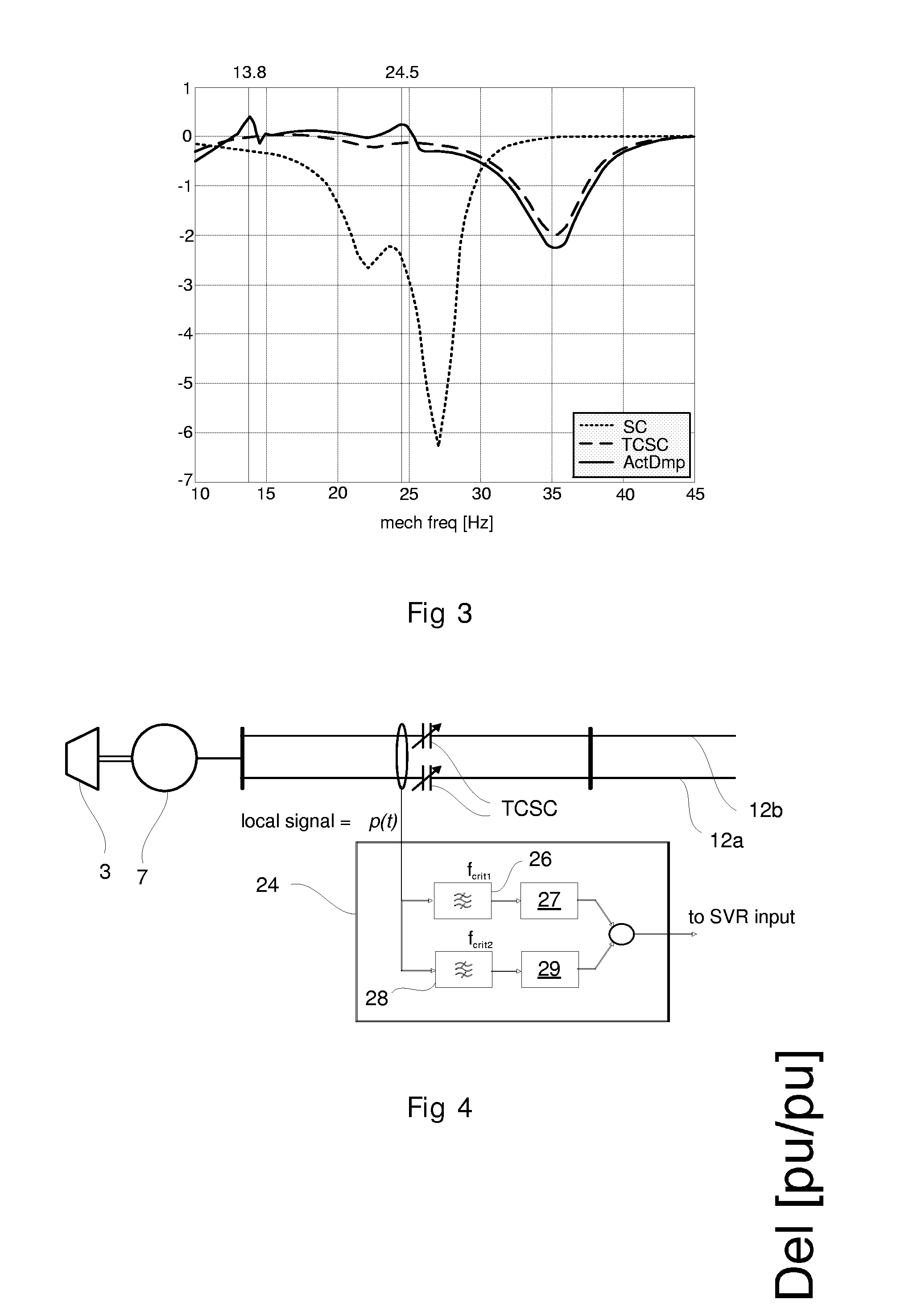
[0023]An ideal damping system takes the speed variation of the generator as input and controls an actuator that produces a proportional breaking torque variation. However, normally the generator is positioned remote from the series capacitor installation and it is difficult and expensive to provide secure signal transmission with sufficient small delay. Utilizing local signals that are as tightly related to the generator speed variation as possible is thus advantageous.

Problems solved by technology

Oscillations of active power in power transmission systems may arise in corridors between generating areas and load areas as a result of poor damping of the interconnection, particularly during heavy power transfer.
It may cause a torsional oscillation with very high amplitude in the turbine-generator shaft system.
Such oscillation induces very high mechanical stress in the shaft.
The main obstacle is that it is very difficult to determine a definite value of mechanical damping.
It is not possible, however, to get guaranteed calculated values during the design stage.

Method used


Image

  • Thyristor controllied series capacitor adapted to damp sub synchronous resonances
  • Thyristor controllied series capacitor adapted to damp sub synchronous resonances
  • Thyristor controllied series capacitor adapted to damp sub synchronous resonances

Examples


Embodiment Construction

[0036]FIG. 1 illustrates mechanical system 1 connected to an electrical system 2. The mechanical system comprises a turbine 3 and the rotor part 4 of a generator 5 connected to the turbine with a shaft 6. The electrical system comprises the stator part 7 of the generator and the network 8 connected to the generator. The mechanical shaft system is characterized by the small-signal transfer function from applied torque deviation to shaft speed deviation (“Turbines & Shaft system”). The electrical system can be represented by the block “Generator & el transm system”, which has the transfer function from applied speed deviation to electrical torque deviation. These two transfer functions are connected in cascade. The stability of the feed-back system is determined by the properties in the electrical system.

[0037]When the shaft speed of the generator is modulated with frequency fmech its phase relative the rest of the electrical network will vary with the same frequency. The active power...


PUM


Abstract

An apparatus for controlling a thyristor controlled series capacitor connected to a power transmission line. A thyristor firing control includes a unit for effectuating a desired capacitor voltage zero crossing in dependence of a line current and a capacitor voltage in response to a command signal. A command control provides the command signal to the thyristor firing control. The command control includes a damping control including a damper configured to damp at a least one discrete frequency.

Description

TECHNICAL FIELD[0001]The present invention concerns control of oscillations in an electric power system. Especially the invention concerns such control by means of a thyristor controlled series connected capacitors (TCSC). The electric power system comprises an electric circuit and a mechanical circuit in cooperation. The mechanical circuit comprises an electric generator and a turbine connected to each other by a shaft. In particular the invention concerns damping of subsynchronous resonances (SSR) in such a power systemBACKGROUND OF THE INVENTION[0002]Oscillations of active power in power transmission systems may arise in corridors between generating areas and load areas as a result of poor damping of the interconnection, particularly during heavy power transfer. Such oscillations can be excited by a number of reasons such as line faults or a sudden change of generator output or loading.[0003]The control offered by TCSC is an ‘impedance’ type control. The inserted voltage is propo...

Claims


Application Information

Patent Timeline
Patent Type & Authority Applications(United States)
IPC IPC(8): H02J3/24
CPCY02E40/14H02J3/1807Y02E40/10
Inventor ASPLUND, GUNNARZHOU, CHANGCHUNLIU, QUIANJIN
Owner ABB POWER GRIDS SWITZERLAND AG
Learn More