
Wheelhouse Inner Bracket for Automotive Vehicles

a technology for automotive vehicles and inner brackets, which is applied in vehicle arrangements, roofs, transportation and packaging, etc., can solve the problems of ineffective reinforcement design solutions, over weight, and increased torsional rigidity, and achieve the effect of superior structural continuity

Inactive Publication Date: 2010-06-03
FORD GLOBAL TECH LLC
View PDF4 Cites 30 Cited by
  • Summary
  • Abstract
  • Description
  • Claims
  • Application Information

AI Technical Summary

Benefits of technology

[0006]It is an object of this invention to overcome the aforementioned disadvantages of the known prior art by providing a reinforcement bracket located inside the rear side rail in alignment with the shock and the underbody cross member to create superior structural continuity in the rear underbody architecture.
[0008]It is an advantage of this invention that when aligned with the C-pillar and the roof header body structure, the reinforcement bracket creates a structural ring that results in a lighter weight structure having a better NVH & Durability vehicle performance.
[0011]It is another advantage of this invention that the reinforcement bracket creates a superior structural continuity in the rear underbody architecture of the automotive vehicle.
[0012]It is still another advantage of this invention that the reinforcement bracket provides improvements in static & dynamic body stiffness plus improvements in rough road NVH vehicle performance.
[0014]It is yet another object of this invention to provide a wheelhouse reinforcement bracket for an automotive vehicle that is durable in construction, inexpensive of manufacture, carefree of maintenance, facile in assemblage, and simple and effective in use.

Problems solved by technology

This known reinforcement structure for the wheelhouse not located strategically well and does not provide an effective connection into the existing back-up structure in the underbody, which leads to over cost, over weight and ineffective reinforcement design solutions for increasing torsional rigidity.

Method used


Image

  • Wheelhouse Inner Bracket for Automotive Vehicles
  • Wheelhouse Inner Bracket for Automotive Vehicles
  • Wheelhouse Inner Bracket for Automotive Vehicles

Examples


Embodiment Construction

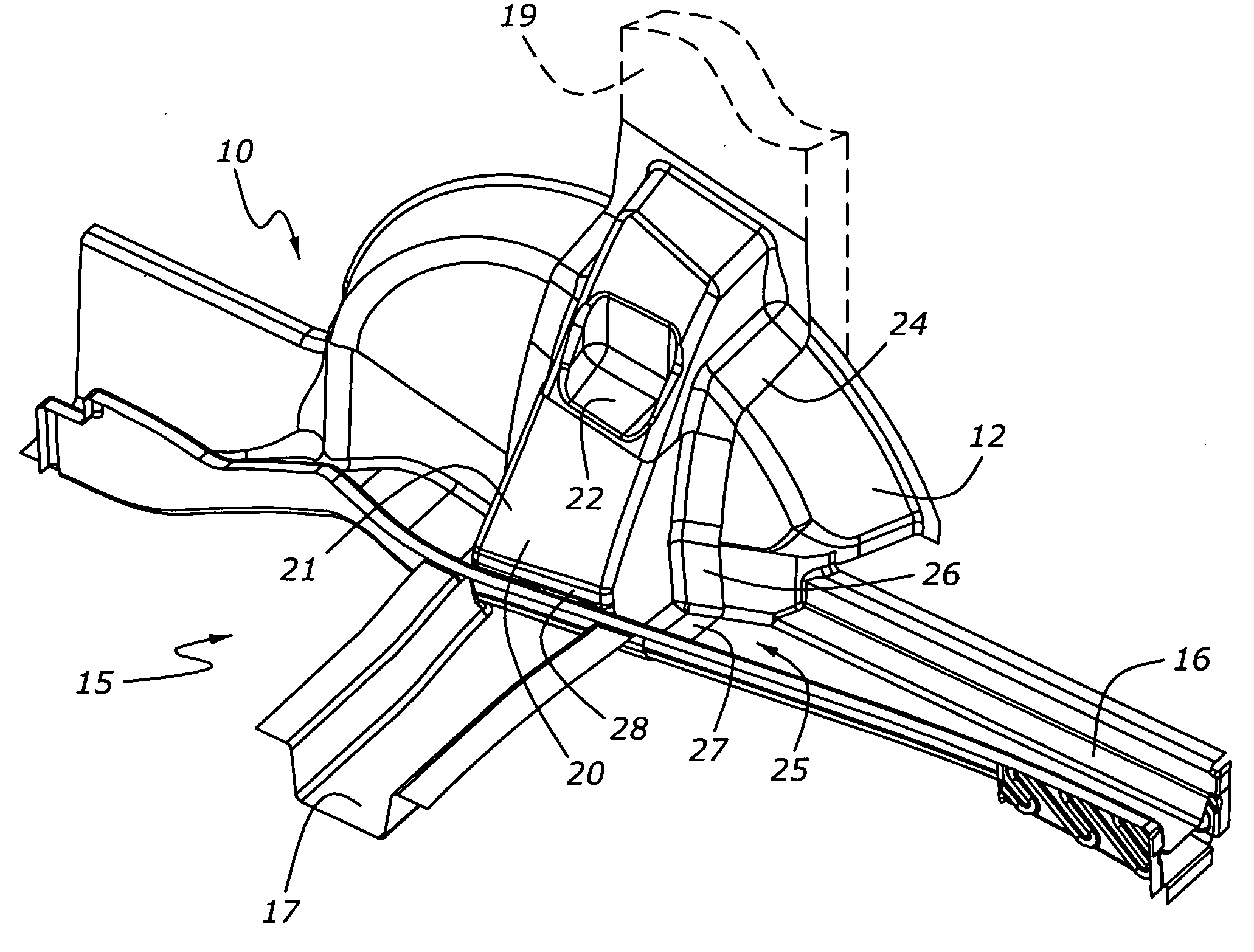
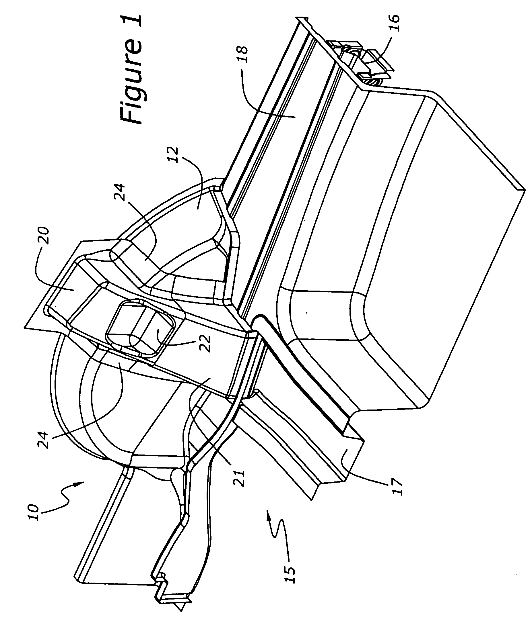
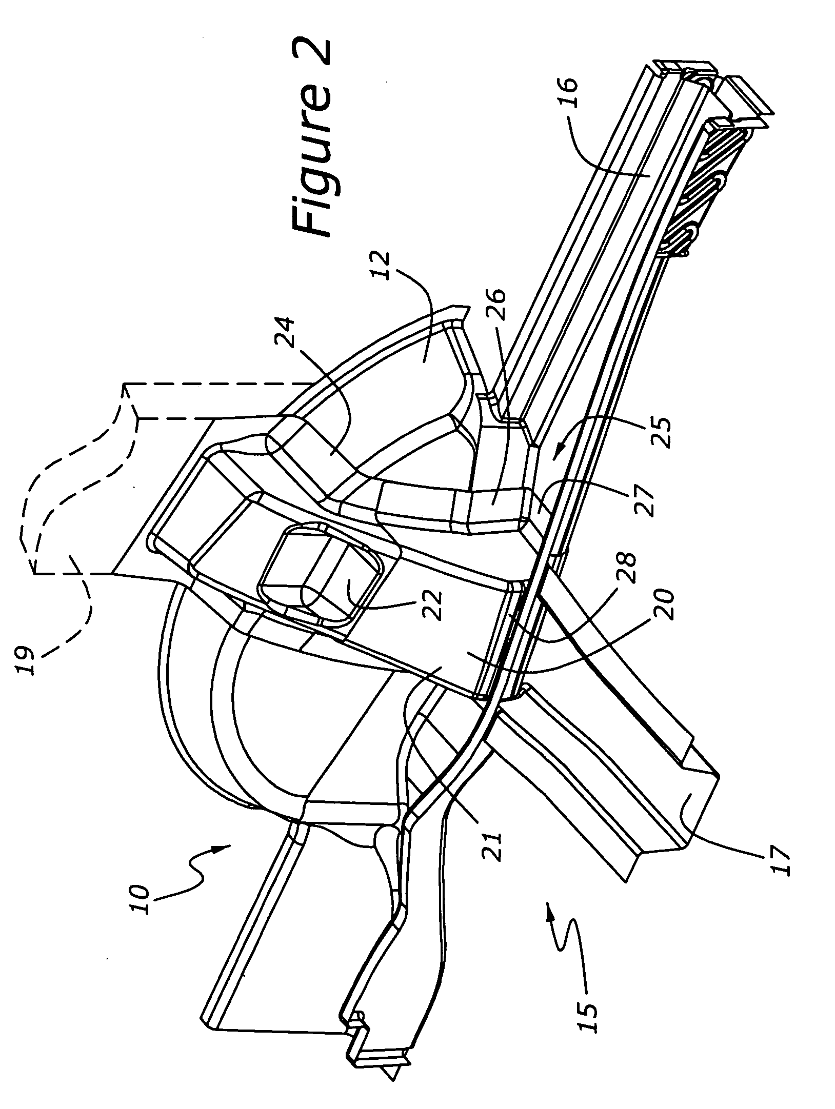
[0021]Referring to the drawings, a wheelhouse bracket incorporating the principles of the instant invention can best be seen. The wheelhouse bracket 20 is welded to each of the wheelhouse structures 12 of an automotive vehicle 10, a representative one of which is partially shown in FIGS. 1 and 2. The wheelhouse structure 12 is a curved member that provides space for the mounting of one of the wheels (not shown) of an automobile 10 so that the wheel is positioned within the transversely extending structure of the vehicle 10. As is well known in the automotive arts, the wheel has associated therewith a suspension mechanism (not shown) which includes a shock absorber (not shown) that is connected to the body of the vehicle to allow movement of the wheel relative to the vehicle body while moving over the ground surface.

[0022]The conventional unitized construction structure 15 of the automotive vehicle 10 includes a longitudinally extending rear side rail 16 on each opposing transverse s...


PUM


Abstract

A wheelhouse reinforcement bracket is provided for the rear wheelhouses of an automotive vehicle to increase torsional rigidity for the vehicle. The wheelhouse bracket is positioned in alignment with the location on the vehicle body where the shock absorber is located, and in alignment with the rear suspension cross member to create a structural ring formed by the wheelhouse bracket, the C-pillar and the rear suspension cross member. The wheelhouse bracket is formed with a mounting flange positionable within the inside of the U-shaped rear side rail to facilitate welding thereto instead of being welded to the top of the underbody floor structure. The mounting flange has a first portion configured to be mated against a first generally vertically extending wall of the rear side rail and a second portion configured to be mated against a generally horizontally extending wall of the rear side rail.

Description

FIELD OF THE INVENTION[0001]This invention relates to the unitized construction of an automotive vehicle and, more particularly, to a bracket located inside the rear side rail in line with the rear suspension cross member to create superior structural continuity in the rear underbody architecture of an automotive vehicle.BACKGROUND OF THE INVENTION[0002]An automotive body construction includes an underbody and a wheelhouse at which a reinforcement bracket is typically positioned on top of the floor of the underbody to increase torsional rigidity. This known reinforcement structure for the wheelhouse not located strategically well and does not provide an effective connection into the existing back-up structure in the underbody, which leads to over cost, over weight and ineffective reinforcement design solutions for increasing torsional rigidity.[0003]An example of a known wheelhouse reinforcement structure can be seen in U.S. Pat. No. 7,021,703, issued to Toshiyuki Yamaguchi, et al, ...

Claims


Application Information

Patent Timeline
IPC IPC(8): B62D27/02B62D25/00B60R99/00
CPCB62D25/088B62D25/2027B62D25/16
Inventor LEONETTI, PHILIP JOHNCARPENTER, RON ALLENGALLAGHER, STEVE WILLIAM
Owner FORD GLOBAL TECH LLC
Learn More