
Wristband and clasp therefor

a wristband and clasp technology, applied in the field of wristbands and clasps, can solve problems such as wristbands on the skin of patients

Active Publication Date: 2010-06-03
PRECISION DYNAMICS CORPORATION
View PDF16 Cites 21 Cited by
  • Summary
  • Abstract
  • Description
  • Claims
  • Application Information

AI Technical Summary

Benefits of technology

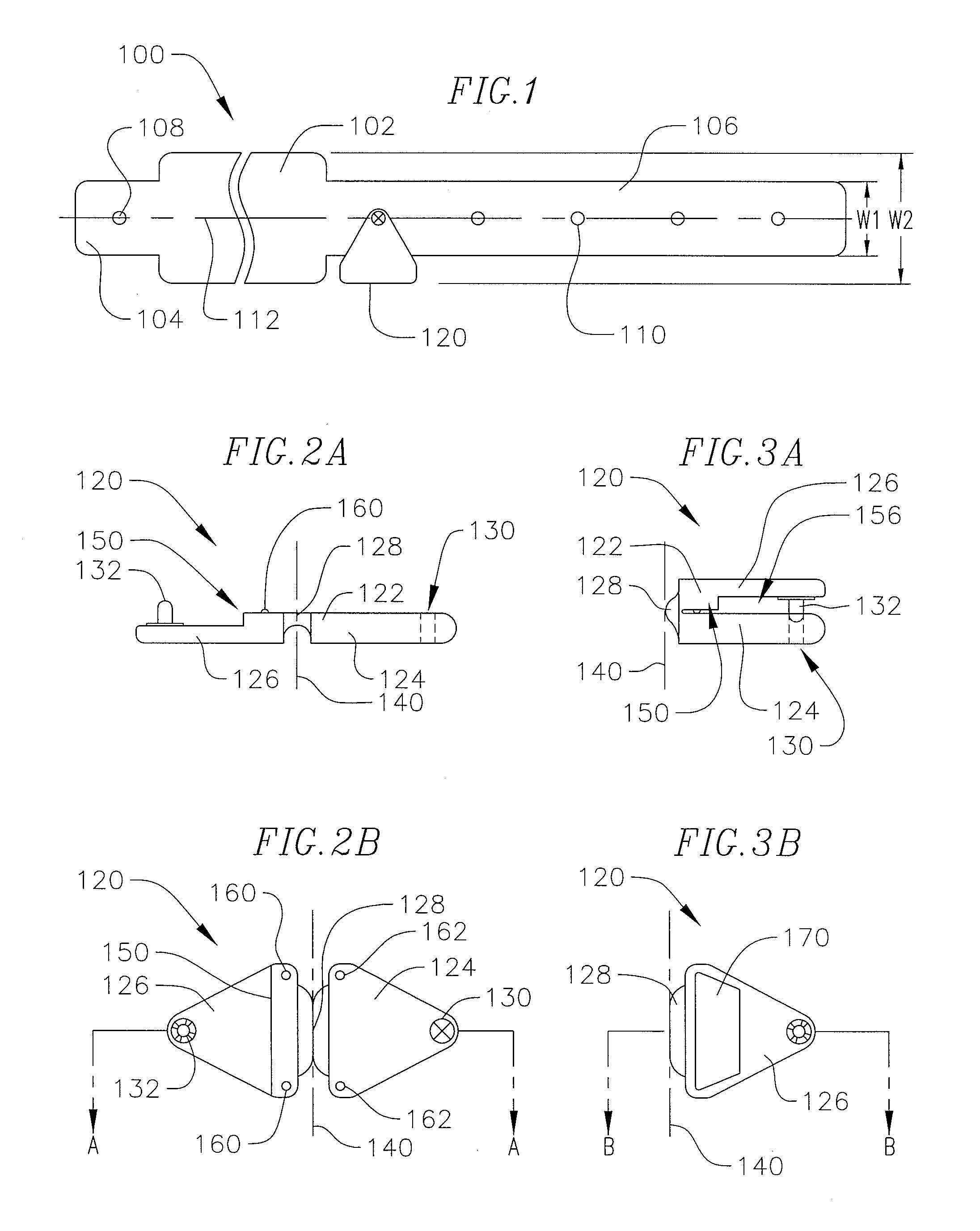
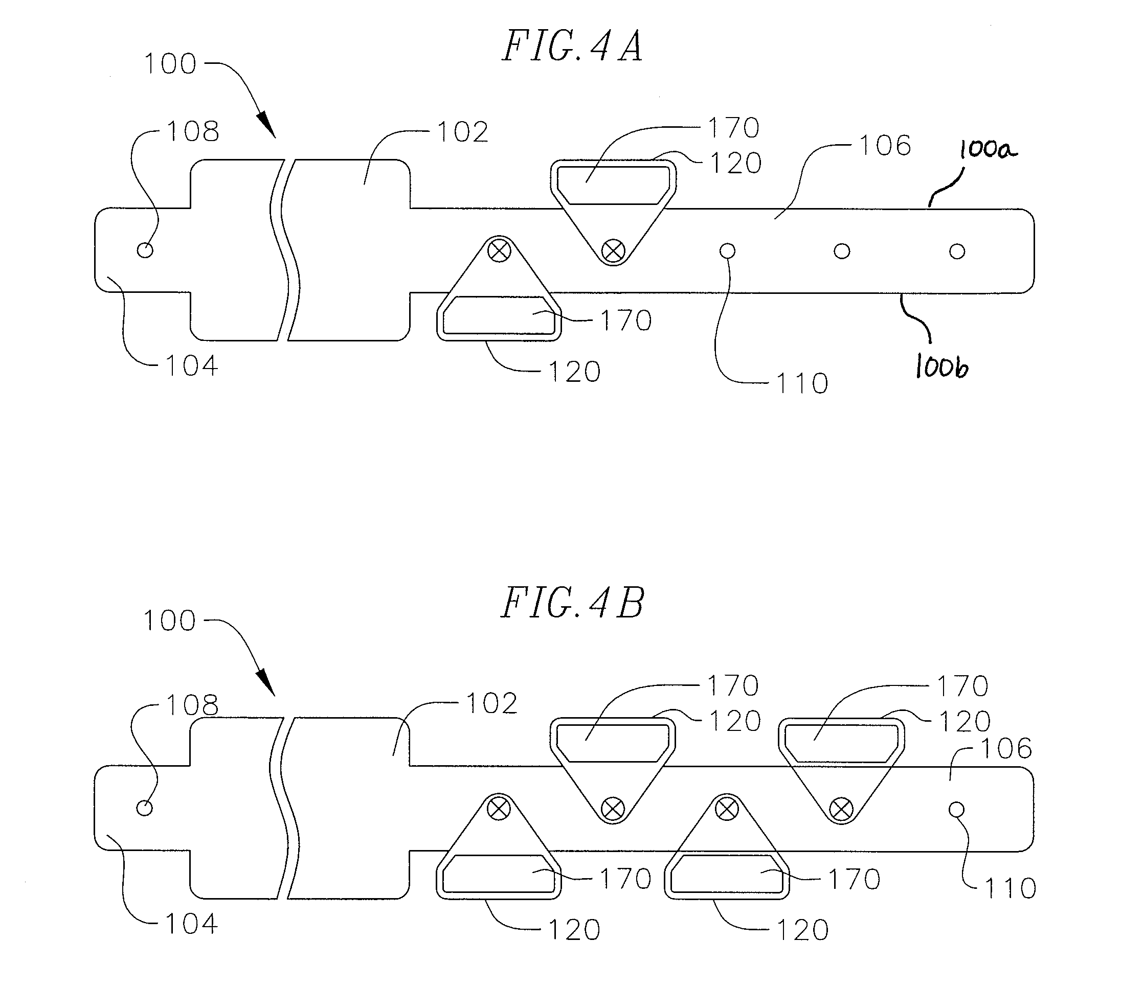
[0005]In one embodiment, an identification assembly includes a band (such as a wristband) and one or more clasps that provide information about the patient. The clasps are color-coded, with the color of the clasp indicating information about the patient (such as an allergy), and they are imprinted with words or symbols that also provide information about the patient (such as the words “Allergy” or “No Latex”). The clasps may be used to secure the band into a loop, but they can also be attached to the band without performing that function. Multiple clasps can be secured to the band at various positions along the band to provide the desired information about the wearer. In one embodiment, the clasps are tapered, such as trapezoidal or triangular, so that clasps secured from opposite edges of the band internest in an alternating arrangement, saving space along the wristband and providing a smaller footprint and more comfort for the wearer. In one embodiment, the color-coded, symbol-imprinted clasps are formed as a single integrated piece, such as a continuous molded plastic piece.

Problems solved by technology

However, the single stem often results in twisting of the wristband on the patient's skin, which can often be uncomfortable.
However, two stems often require a larger sized clasp, which can be cumbersome.

Method used


Image

  • Wristband and clasp therefor
  • Wristband and clasp therefor
  • Wristband and clasp therefor

Examples


Embodiment Construction

[0039]Reference will now be made to the drawings wherein like numerals refer to like parts throughout.

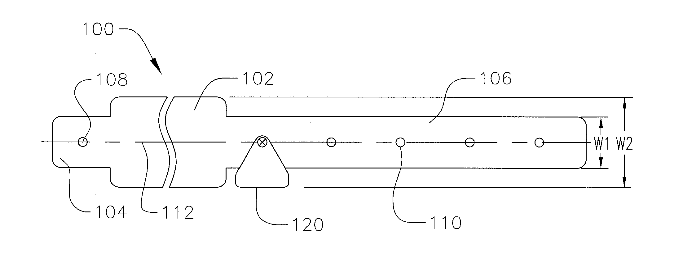
[0040]An embodiment of a wristband 100, as shown in FIG. 1, has a display portion 102 for displaying identification information and fastening portions 104, 106 with one or more attachment apertures 108, 110 formed therein for securing a clasp, clip or snap device 120 thereto. In one aspect, the fastening portions 104, 106 have a width (w1) that is smaller than a width (w2) of the display portion 102, and the fastening portions 104, 106 extend along a central axis 112 of the display portion 102 of the wristband 100 so that the width (w1) of the fastening portions 104, 106 is centered within the width (w2) of the display portion 102 of the wristband 100.

[0041]As shown in FIG. 1, a first fastening portion 104 extends from one end of the display portion 102 and a second fastening portion 106 extends from the other end of the display portion 102. In one embodiment, the first fastening po...


PUM


Abstract

The field of the present invention relates to an identification assembly, and in particular, to a clasp device for securing to an identification wristband, and to a wristband and clasp assembly. In one embodiment, a identification assembly for a patient includes a band with first and second opposite ends and first and second opposite edges and a width measured between the first and second edges. The identification assembly also includes a clasp secured to the band. The clasp has a first section having an inside surface and an outside surface; a second section having an inside surface and an outside surface, the inside surface of the second section facing the inside surface of the first section; and a protrusion extending from one of the first or the second section to engage the other of the first or the second section to secure the first and second sections together in a closed position. The outside surface of one of the first or the second section comprises a symbol on the outside surface to provide information about the patient. The clasp is color-coded to provide information about the patient.

Description

CROSS-REFERENCE TO RELATED ED APPLICATION(S)[0001]This application is a continuation in-part of U.S. patent application Ser. No. 11 / 558,401, filed on Nov. 9, 2006 and published as U.S. Publication No. 2008-0110069, which is hereby incorporated by reference in its entirety for all purposes as if fully set forth herein.FIELD OF THE INVENTION[0002]The field of the present invention relates to an identification assembly, and in particular, to a clasp device for securing to an identification wristband, and to a wristband and clasp assembly.BACKGROUND[0003]Wristbands are used in hospitals to identify patients and for similar purposes in other instructional / institutional settings. In general, a wristband is attached to a patient's wrist or other appendage, such as a patient's ankle, with a fastener. Conventional wristbands have two ends and a plurality of holes along the length of the wristband. Typical fasteners are rectangular with a large footprint and have one or two stems or posts tha...

Claims


Application Information

Patent Timeline
IPC IPC(8): A61B5/117
CPCG09F3/005A44C5/0015Y10T24/44769Y10T24/4016Y10T24/44026Y10T24/3944Y10T24/4023Y10T24/44889Y10T24/3916Y10T24/1498
Inventor MCDERMOTT, ROBERTPREISACH, ADAMBISHOP, ANDREWCARPENTIER, TRACEYJOSEPH, KAREN
Owner PRECISION DYNAMICS CORPORATION
Learn More