
Method for identifying and analyzing faults/fractures using reflected and diffracted waves

Active Publication Date: 2010-05-27
GEOMAGE 2003
View PDF26 Cites 37 Cited by
  • Summary
  • Abstract
  • Description
  • Claims
  • Application Information

AI Technical Summary

Benefits of technology

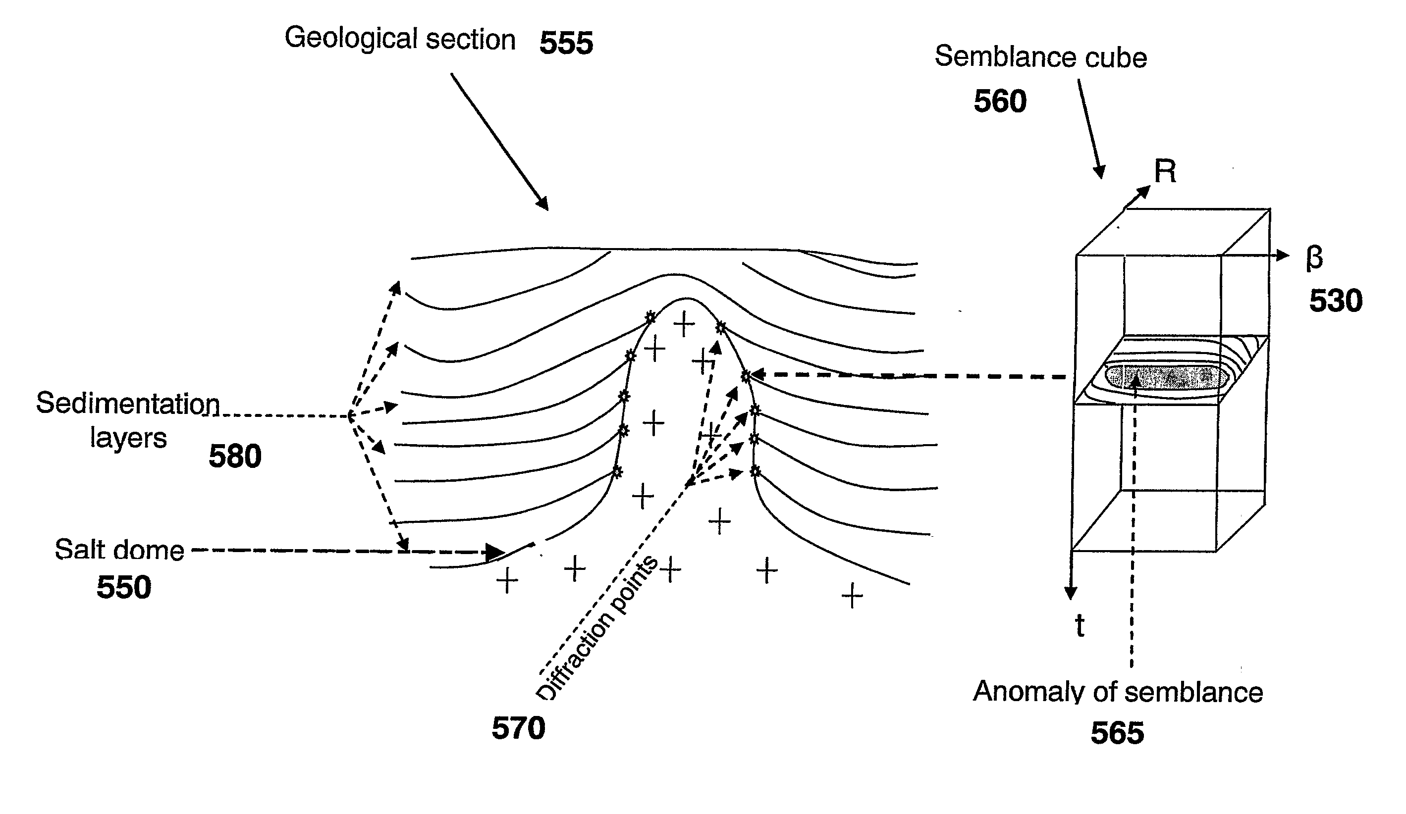
[0029]Accordingly, it is a principal object of the present invention to provide a method for separating the diffraction and reflection of seismic waves using two parameters of the wave selection: β and R, and by using transformations obtaining a new image for each pixel (image point), which accumulates the energy of the diffracted and reflected waves.
[0032]The present invention relates to the field of computer aided exploration for hydrocarbons using seismic multifold data processed using the procedure of multifocusing scanning of the main parameters of the wave field. These parameters are angle of incidence of the wave front and its radius of curvature connected with velocity in the subsurface. Such scanning allows determination of the cube of data for each central trace of the seismic stack S(β,R,t), and gives an opportunity for the separation of the wave field into reflection and diffraction components.

Problems solved by technology

The methods which use correlation coefficients between adjacent seismic traces, derivative difference, amplitude difference, eigenvalues and other statistical parameters derived from adjacent seismic traces require time consuming, manual interpretation of the geologic faults and fractures.
However, each of these methodologies requires the manual interpretation of the geologic faults, which is time consuming.
This may lead to identification of false disturbances interpreted as faults.
Deficiencies of this method consist in its dependence on artifacts connected with a Radon-transform and exactness of velocity analysis.
In general, interference, multiple reflections or artifacts introduce regular and irregular noise, which sometimes renders the image of the subsurface difficult to interpret.
CMP stacking is used for suppression of noise and multiples, but it does not give the desired result in the case of small folding.

Method used


Image

  • Method for identifying and analyzing faults/fractures using reflected and diffracted waves
  • Method for identifying and analyzing faults/fractures using reflected and diffracted waves
  • Method for identifying and analyzing faults/fractures using reflected and diffracted waves

Examples


Embodiment Construction

[0046]The principles and operation of a method and an apparatus according to the present invention may be better understood with reference to the drawings and the accompanying description, it being understood that these drawings are given for illustrative purposes only and are not meant to be limiting.

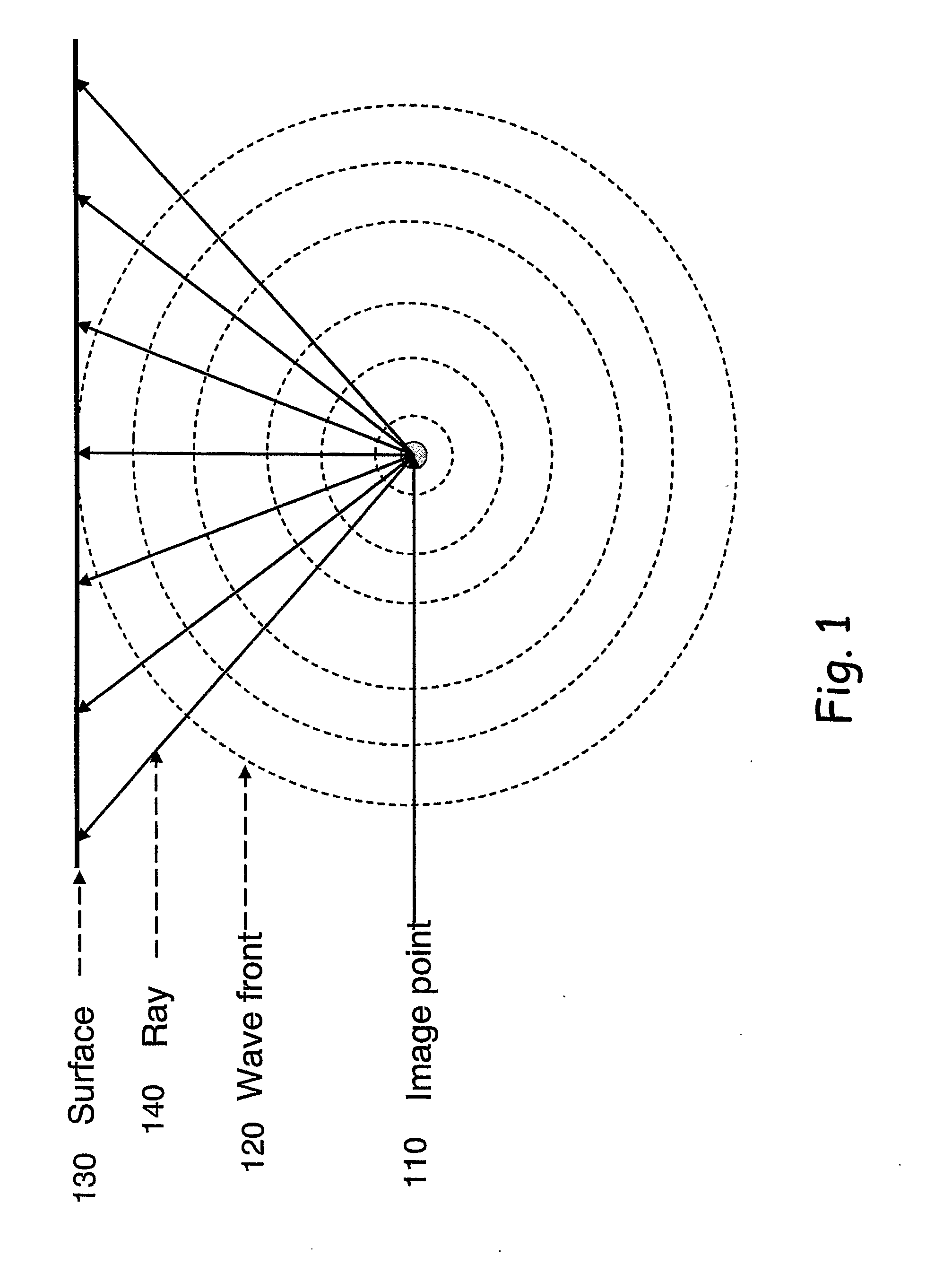
[0047]Reference is now made to FIG. 1, showing a diagrammatic representation of the diffracted wave spreading from the image point, in accordance with the principles of the present invention. In FIG. 1, the diffracted wave, being extended from the image point 110 on the boundary, distributes energy evenly along the wave front 120 in the ideal case. Thus, the seismic receivers, located evenly on a certain base on the surface 130 above the source of the rays 140 of the diffracted wave, will register fluctuations from it with the approximately identical amplitude.

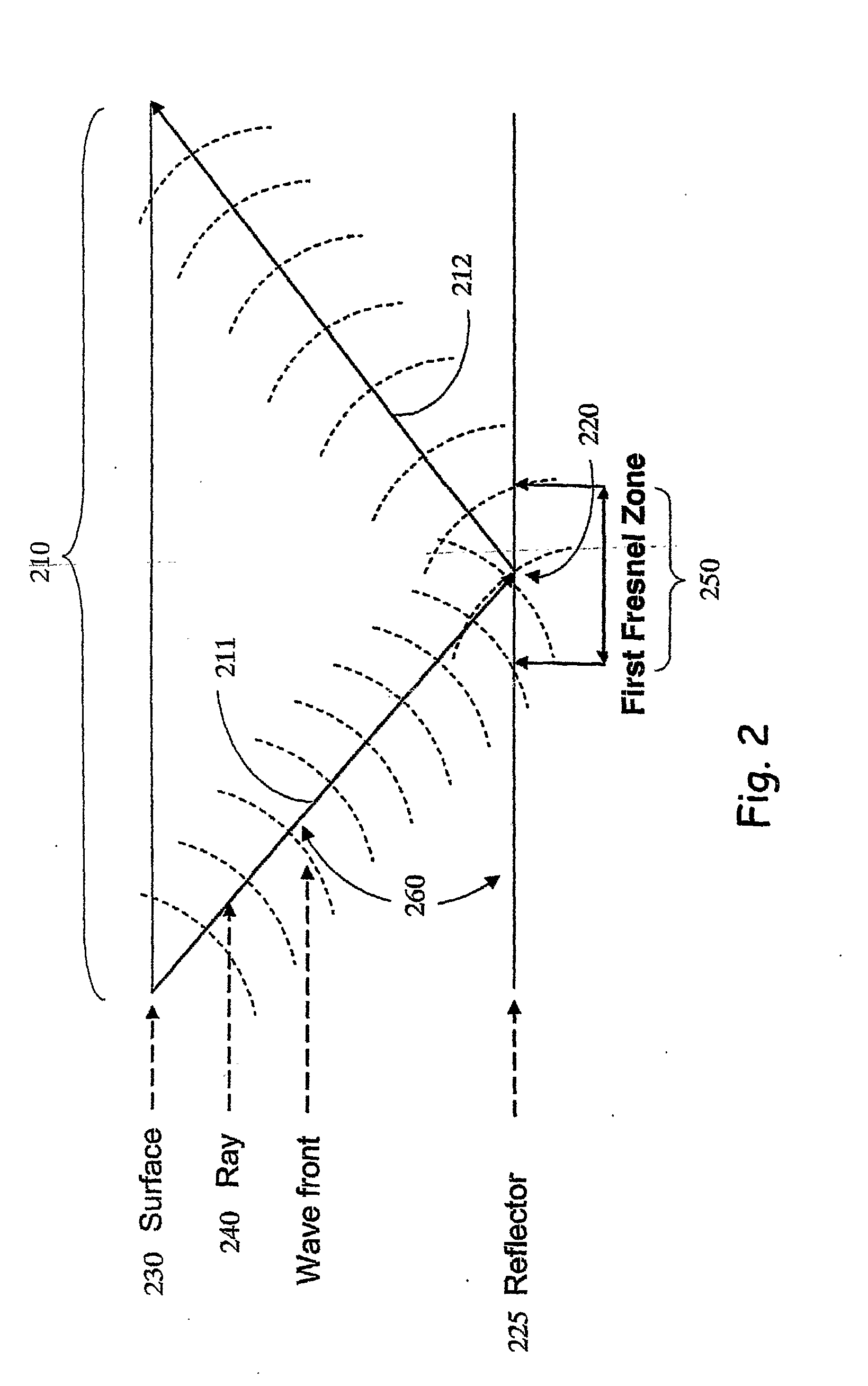
[0048]FIG. 2 is a diagrammatic representation of the wave distribution within the limits of the aperture 210, comprising an inc...


PUM


Abstract

A method for fault and fracture identification based on seismic data representing a geological section using dispersion properties of reflected and diffracted waves. The method includes scanning N parameters associated with the seismic data. The array includes the coordinate axes of the angle of emergence (β), the radius of curvature of the wave front (R) and either time or depth samples. The method also includes processing the N parameters, generating a new image having a cross-sectional shape associated with one of the reflected and diffracted waves, calculating parameters DS and LS, evaluating DS for the case of fracture characterization, and comparing, for the case of fault identification, parameter LS with a threshold value defining the type of wave as one of the reflected and diffracted wave, the cross-sectional shape being substantially circular for the reflected wave, and being elliptical for the diffracted wave.

Description

FIELD OF THE INVENTION[0001]The present invention relates generally to computer aided exploration for hydrocarbons using seismic data, and more particularly, the invention relates to a computer implemented method for identifying, imaging and analysis of faults / fractures from seismic data using dispersion properties of reflected and diffracted waves both for 2-D and 3-D seismic data.BACKGROUND OF THE INVENTION[0002]The prediction of faulting and fracturing is very important in oil and gas exploration and production. The reservoirs in which hydrocarbons have been located include clastics (sandstones etc.) and carbonates (limestones etc). Faulting has general value for both types of rocks, but distribution of fracture in carbonates is a particular target of the development of oil and gas fields.[0003]Traditional techniques use the time, amplitude and velocity attributes of reflected waves to recognize stratigraphic features and sudden changes of attributes interpreted as faulting. The ...

Claims


Application Information

Patent Timeline
IPC IPC(8): G01V1/28G06F19/00
CPCG01V1/32
Inventor BERKOVITCH, ALEXSCHARFF, NATHANBELFER, IGOR
Owner GEOMAGE 2003
Learn More