Catheter drainage system
a drainage system and catheter technology, applied in medical science, diagnostics, vaccine/ovulation diagnostics, etc., can solve the problems of potential lethal sepsis, and increased risk of sepsis, and achieve the effect of less tension
- Summary
- Abstract
- Description
- Claims
- Application Information
AI Technical Summary
Benefits of technology
Problems solved by technology
Method used
Image

Examples
example 1
Collection Bags
[0085]Collection bags have been designed that provide features configured to minimizing backpressures in the drainage tube (and ultimately the catheter). The collection bag is a plastic bag of round or rounded-triangle shape. This bag is designed for use lying flay on the ground. The drainage tube can be similar in design to currently available products and can possess non-proprietary features, such as, e.g. urine sampling port.
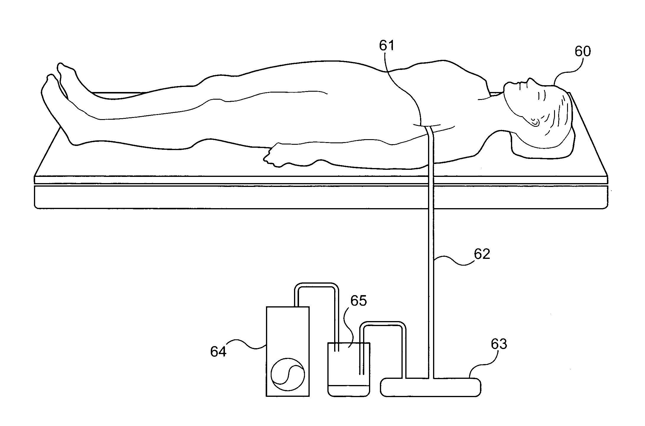
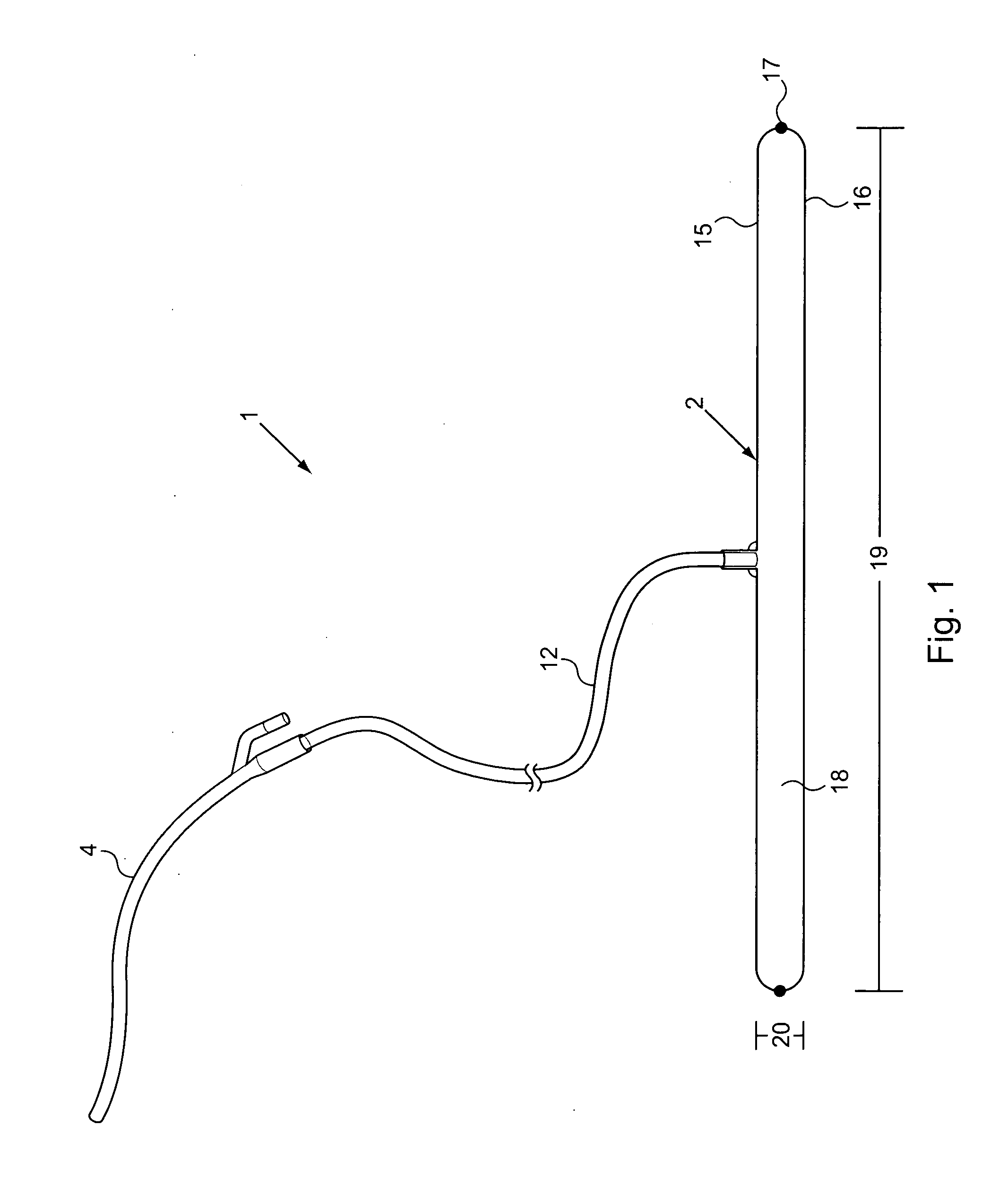
[0086]The following is a description of a proposed “flat” drainage bag, e.g., as shown in FIG. 3A. The proposed fluid collection system 1, used as intended, lies flat on ground. That is, e.g., the proposed device is designed with a drainage bag to be used laying in a flat position, on a horizontal surface, such as the ground, a floor, on a dedicated “pad”, basin resting on the floor, and / or the like. The drainage collection bag 2, can lay flat directly on the horizontal surface or on a clean “drainage bag pad”3. In use, catheter 4 is typically ...
example 2
Urometers
[0106]Urometers can be integrated into drainage collection systems of the invention. In preferred embodiments the urometer is integral to the collection bag. For example, the urometer can be a smaller chamber associated with the main collection bag to first receive drainage from the tube and having volume graticule hatch marks for reading fluid volumes received.
[0107]Urometers can be fabricated from a hard clear plastic, or from a soft flexible plastic that distends upwards as the urometer is filled. When the user wants to visually measure the fluid content inside (soft urometer), the bag is manually suspended by the top of the urometer so that the fluid fills uniformly the urometer chamber. Hatchmarks indicate the volume within the urometer.
[0108]An exemplary urometer design can be “a cup within a cup”, where the drainage tube connects to the top of the urometer cup, and fluid collects inside the urometer. When the urometer cup is sufficiently filled, the cup is tilted ove...
example 3
Other Design Aspects
[0117]The fluid drainage systems can include additional features to enhance performance.
[0118]I. Plastic “elevator balls” (disposable, foam or biodegradable Styrofoam, or other material) that can be snapped onto the drainage tube anywhere along its length, to maintain the drainage tubing at a minimum height from the ground. Each ball can be solid or hollow or partially hollow, etc. Each ball can possess a partial-thickness slit or groove to allow the drainage tube to fit snugly into the ball. Each ball need not be strictly spherical in shape. The purpose of the ball is to provide clearance beneath the drainage tube so that the drainage tube retains a minimum elevation. The elevator ball would most typically be used close to where the drainage tube joins to the bag, where it would otherwise be more likely to “dip” with gravity, below the level of the juncture between the tube and bag.
[0119]II. “Telescoping tubing” is a means by which redundancy in tubing length ca...
PUM
 Abstract
Description
Claims
Application Information
 - R&D
- Intellectual Property
- Life Sciences
- Materials
- Tech Scout
- Unparalleled Data Quality
- Higher Quality Content
- 60% Fewer Hallucinations
Browse by: Latest US Patents, China's latest patents, Technical Efficacy Thesaurus, Application Domain, Technology Topic, Popular Technical Reports.
© 2025 PatSnap. All rights reserved.Legal|Privacy policy|Modern Slavery Act Transparency Statement|Sitemap|About US| Contact US: help@patsnap.com