
Damper mechanism

a technology of hysteresis torque and mechanism, which is applied in the direction of friction clutches, vibration suppression adjustments, and gaps in rotational directions, can solve the problems that the gap in rotational direction cannot be considered an effective approach, and noise may be generated during idle, so as to achieve the desired hysteresis torque reliably

Inactive Publication Date: 2010-05-27
EXEDY CORP
View PDF13 Cites 10 Cited by
  • Summary
  • Abstract
  • Description
  • Claims
  • Application Information

AI Technical Summary

Benefits of technology

[0012]A first object of the present invention is to provide a damper mechanism with which the desired hysteresis torque is reliably generated.
[0014]A second object of the present invention is to improve reliably the torsional vibration damping performance of a damper mechanism.
[0016]A third object of the present invention is to afford greater latitude in the design of a damper mechanism.
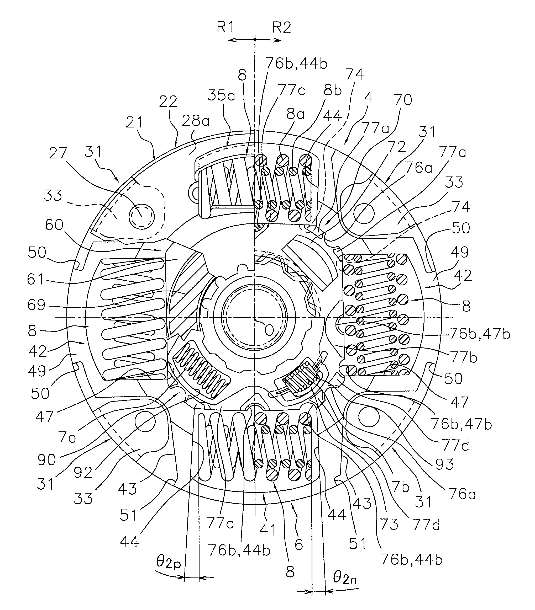
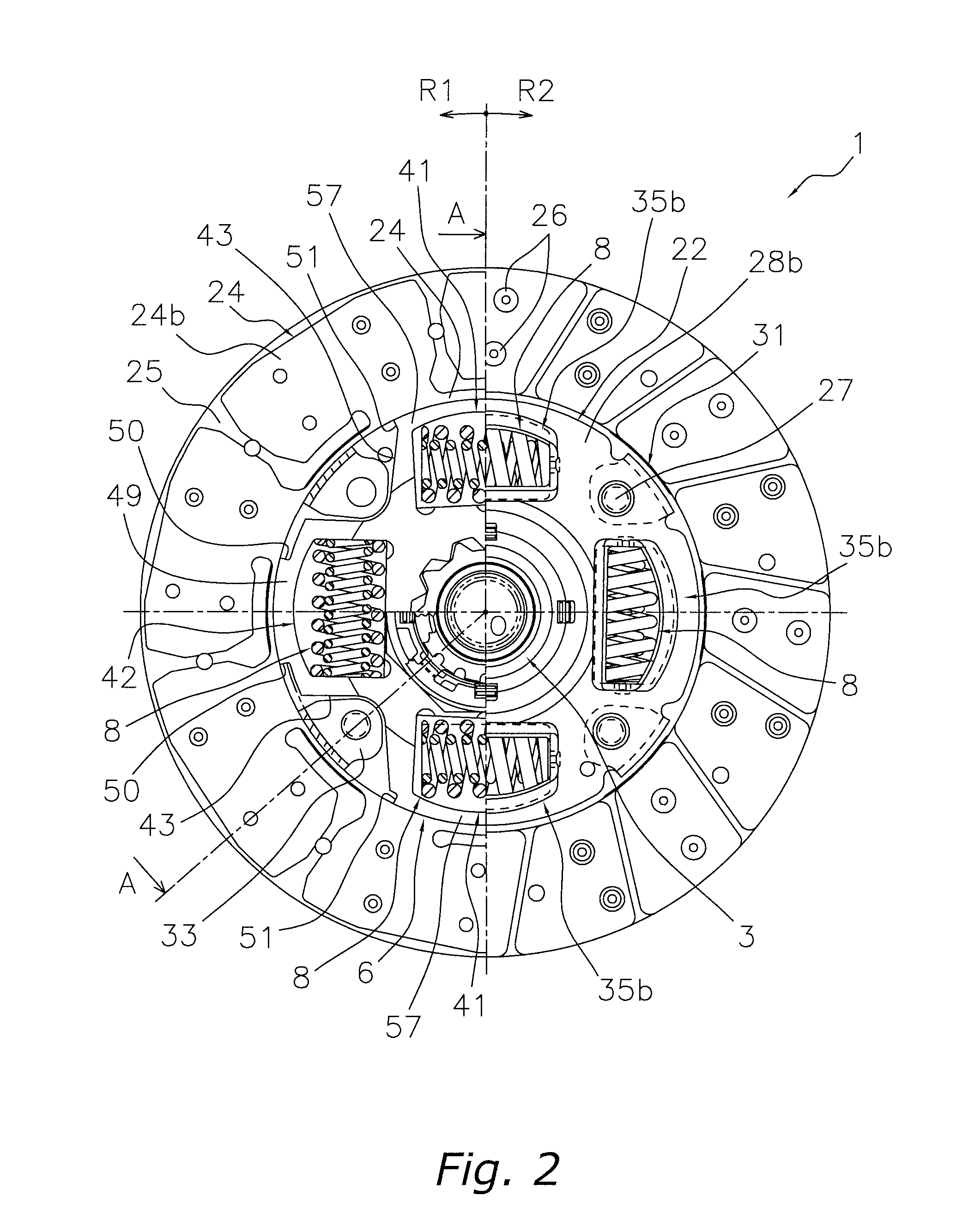
[0018]With this damper mechanism, when the first rotary body rotates with respect to the second rotary body, the friction member of the first member slides with the first rotary body. At this point, since the first and second members are incapable of rotation with respect to the second rotary body, even if the relative rotational angle between the first rotary body and the second rotary body is small, hysteresis torque will still be generated between the first and second rotary bodies. This means that the desired hysteresis torque can be reliably generated with this damper mechanism.
[0032]Thus, with this damper mechanism, hysteresis torque can be generated in the second stage region by suitably setting the relationship between the second angle and third angle. The result is that the resistance increases in the rotational direction from the second stage to the third stage, and the torsion angle of the damper mechanism more easily fits within the range of the second stage region, without reaching all the way to the third stage region. That is, it is possible to prevent the generation of the noise of the stopper acting at the boundary between the second and third stages, and to raise torsional vibration damping performance.
[0038]The result of this is that the outside diameter of the damper mechanism is maintained while preventing the first plate member from interfering with the flywheel. That is, there is greater latitude in the design of the damper mechanism.

Problems solved by technology

However, depending on the characteristics of the vehicle body, there may be instances when this gap in the rotational direction impedes the effect that the high hysteresis torque is supposed to have, so ensuring a gap in the rotational direction cannot necessarily be considered an effective approach.
As a result, even with a damper mechanism having a low torsion angle region, there are cases when noise may be generated during idling.

Method used


Image

  • Damper mechanism
  • Damper mechanism
  • Damper mechanism

Examples


first embodiment

5. Modifications of First Embodiment

[0142]The specific constitution of the present invention is not limited to the embodiment given above, and various changes and modifications are possible without departing from the essence of the invention.

(1)

[0143]In the above embodiment, the clutch disk assembly 1 in which the damper mechanism 4 was installed was described as an example, but the present invention is not limited to this. For example, this damper mechanism can also be applied to lockup devices for fluid torque transmission devices, two-mass flywheels, or other such power transmission devices.

(2)

[0144]Also, the layout of the first protrusions 62, the second protrusions 63, and the protrusions 74 is not limited to the above embodiment.

(B) Second Embodiment

1. Overall Configuration of Clutch Disk Assembly

[0145]A clutch disk assembly 101 in which a damper mechanism 104 according to the present invention is installed will be described with reference to FIGS. 18 and 19. FIG. 18 is a simp...

second embodiment

5. Modifications of Second Embodiment

[0194]The specific constitution of the present invention is not limited to the embodiment given above, and various changes and modifications are possible without departing from the essence of the invention.

(1)

[0195]In the above embodiment, the clutch disk assembly 1 in which the damper mechanism 4 was installed was described as an example, but the present invention is not limited to this. For example, this damper mechanism can also be applied to lockup devices for fluid torque transmission devices, two-mass flywheels, or other such power transmission devices.

(2)

[0196]Also, the layout of the first protrusions 162, the second protrusions 163, and the protrusions 174 is not limited to the above embodiment.


PUM


Abstract

A damper mechanism 4 has an input rotary body 2, a hub flange 6, a splined hub 3, a third friction washer 60, a bushing 70, and an output plate 90. The third friction washer 60 is non-rotatably mounted on the hub flange 6 with respect to the hub flange 6, and has a friction member that contacts the input rotary body 2 in the axial direction. The bushing 70 is axially disposed between the hub flange 6 and the third friction washer 60, and is mounted on the hub flange 6 and the third friction washer 60 to be incapable of rotation with respect to the third friction washer 60. The output plate 90 is disposed between the third friction washer 60 and the bushing 70 in the axial direction, and is supported by the splined hub 3 to be capable of rotating integrally with the splined hub 3.

Description

BACKGROUND OF THE INVENTION[0001]1. Field of the Invention[0002]The present invention relates to a damper mechanism, and more particularly relates to a damper mechanism for damping torsional vibration in a power transmission system.[0003]2. Description of the Related Art[0004]A clutch disk assembly used in an automotive vehicle has a clutch function of transmitting and cuffing off torque from the flywheel of an engine to a transmission, and a damper function of absorbing and damping torsional vibration from the flywheel. Vibrations in a vehicle generally include idling noises (rattle), driving noises (acceleration and deceleration rattle and muffled noises), and tip-in and tip-out (low frequency vibrations). The damper function eliminates these noises and vibrations.[0005]Idling noises are noises that sound like rattling and are generated from the transmission when a shifter is in neutral and the clutch pedal is out, such as when waiting at a stop light. What causes this raffling is...

Claims


Application Information

Patent Timeline
Patent Type & Authority Applications(United States)
IPC IPC(8): F16F15/129
CPCF16D13/644F16F15/129F16D13/646
Inventor UEHARA, HIROSHIHASHIMOTO, YASUYUKIHASHIMOTO, HIDEKIYOSHIMURA, YOSHINARI
Owner EXEDY CORP
Learn More