Blower, housing and wind wheel thereof

a technology of wind turbine and housing, which is applied in the direction of wind turbine with perpendicular air flow, waterborne vessels, machines/engines, etc., can solve the problems of increasing development investment, increasing production cost and manufacturing difficulty, and high cost of aluminum-coated or galvanized steel plates, etc., to achieve short development period, reduce production cost, and simple structure

Inactive Publication Date: 2010-05-27
ZHONGSHAN BROAD OCEAN
View PDF17 Cites 1 Cited by
  • Summary
  • Abstract
  • Description
  • Claims
  • Application Information

AI Technical Summary

Benefits of technology

[0008]In view of the above-described problem, it is one objective of the invention to provide a blower that is capable of operating under a high-temperature (60-100° C.) and high-humidity (100%) environment, and features simple structure, easy manufacturing and low production cost.
[0009]It is another objective of the invention to provide a housing for blower that is capable of operating under a high-temperature (60-100° C.) and high-humidity (100%) environment, and features simple structure, easy manufacturing and low production cost.
[0010]It is a further objective of the invention to provide a wind wheel for blower that is capable of operating under a high-temperature (60-100° C.) and high-humidity (100%) environment, and features simple structure, easy manufacturing and low production cost.
[0027]Advantages of the invention comprise: 1) the housing can be made by a stamping process, and is capable of operating under a high-temperature (below 100° C.) and high-humidity (100%) environment; 2) the blower is made of general steel plates, and production cost is reduced by 40% in comparison with conventional aluminum-coated or galvanized steel plates; 3) the blower features simple structure, short development period, low development investment and easy manufacturing; 4) the wind wheel is made of steel plates or BMC resin, and is capable of operating under a high-temperature (below 100° C.) and high-humidity (100%) environment; 5) the body and the bottom plate of the housing facilitates simple structure and easy production; 6) the motor is disposed at the top of the housing via the U-shaped supporter, which simplifies structure of the blower; 7) arrangement of the protruding portion and the lug facilitates simple structure, easy installation and reduced volume; 8) arrangement of the sheet, the capacitor and the protruding portion facilitates simple structure and easy installation.
[0028]Advantages of the housing and the wind wheel of the invention comprise: 1) the housing and the wind wheel can be made by a stamping process, and are capable of operating under a high-temperature (below 100° C.) and high-humidity (100%) environment; 2) the housing and the wind wheel are made of general steel plates, and production cost is reduced by 40% in comparison with conventional aluminum-coated or galvanized steel plates; 3) the housing and the wind wheel feature simple structure, short development period, low development investment and easy manufacturing.

Problems solved by technology

But the aluminum-coated or galvanized steel plates are expensive, and easy to be corroded under a high-temperature (60-100° C.) and high-humidity (100%) environment.
However, the blower made of plastics needs mold opening, the number of molds is large and a development period of the molds is long, which increases development investment, production cost and manufacturing difficulty.
Moreover, the blower has large volume and complex structure.

Method used


Image

  • Blower, housing and wind wheel thereof
  • Blower, housing and wind wheel thereof
  • Blower, housing and wind wheel thereof

Examples


Embodiment Construction

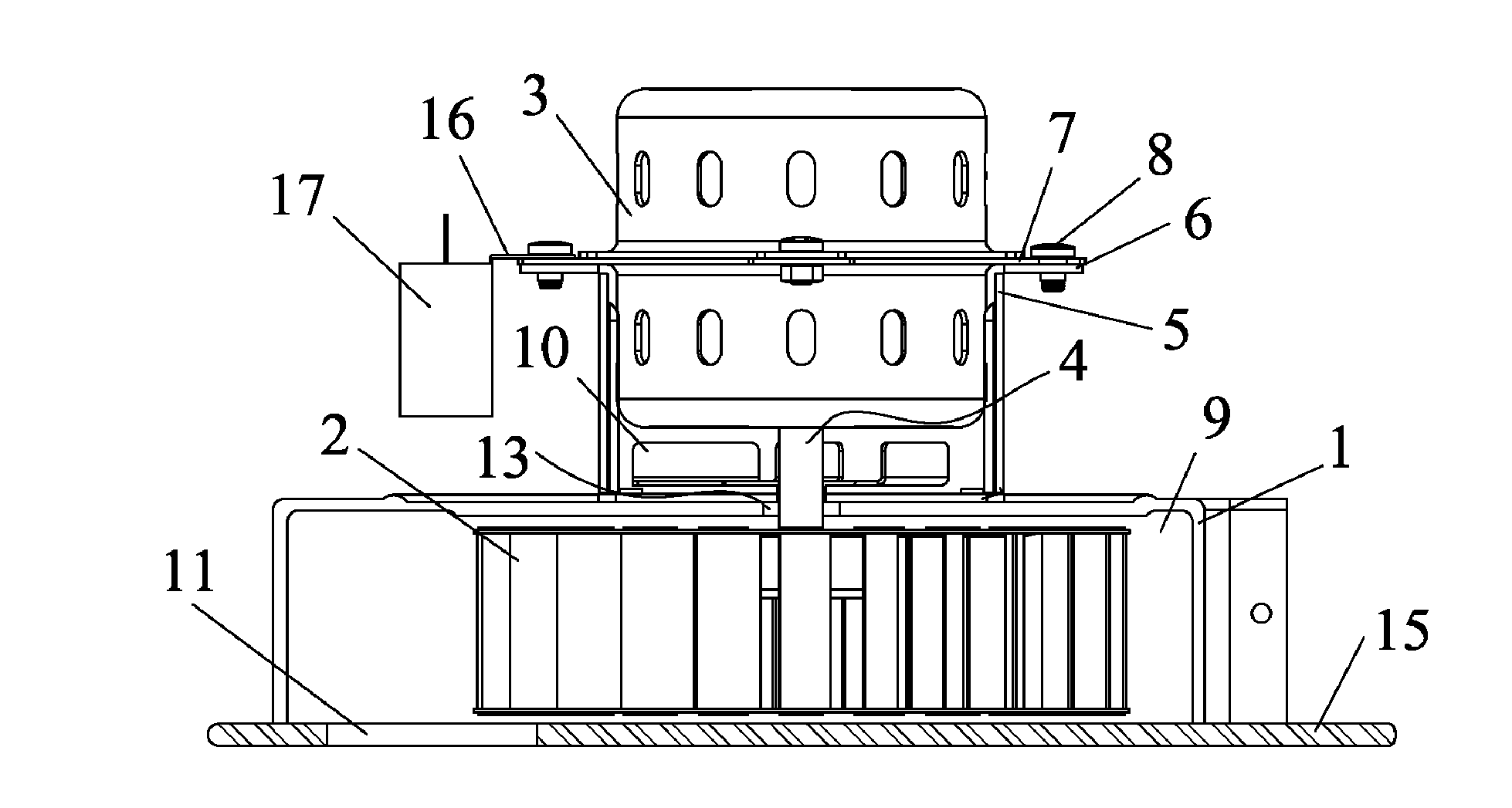
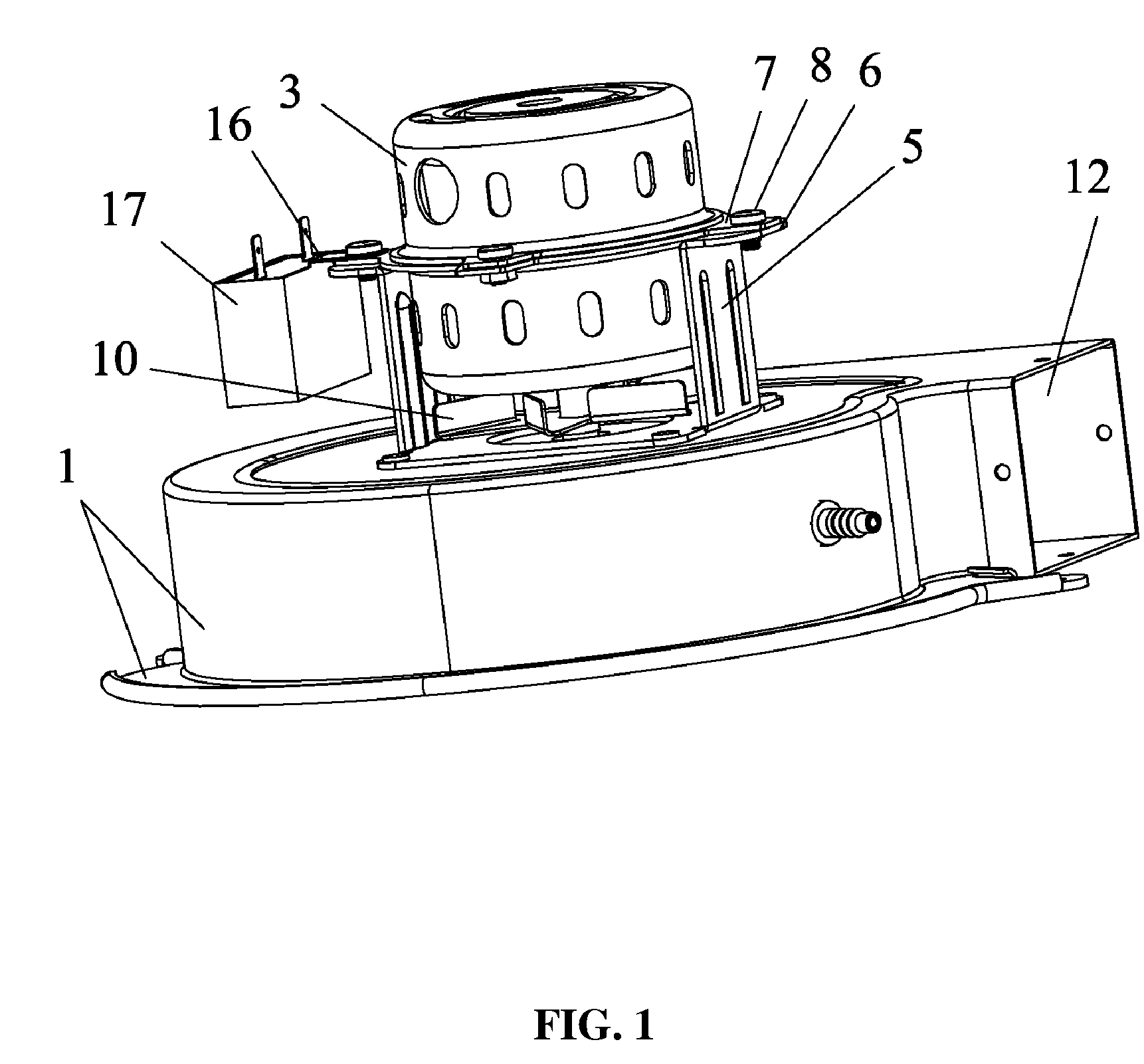
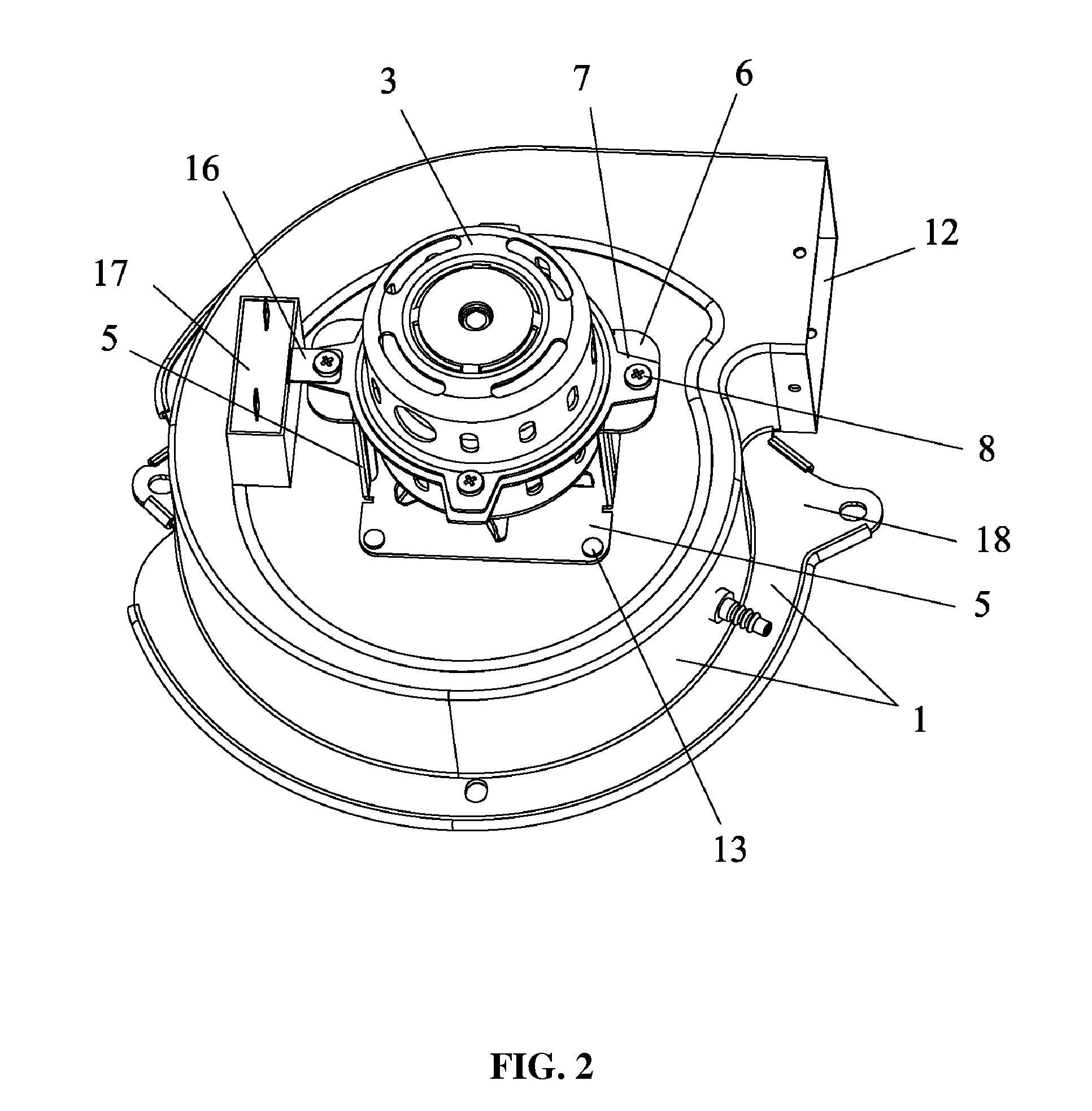
[0035]As shown in FIGS. 1-4, blower of the invention comprises a housing 1, a wind wheel 2, a motor 3, an air inlet 11, and an air outlet 12.

[0036]The housing 1 comprises a cavity 9, a body 14 and a bottom plate 15.

[0037]The housing 1 and the wind wheel 2 are made of steel plates, and enamel materials are coated on surfaces of the steel plates. In another embodiment, the wind wheel 2 is made of BMC resin.

[0038]The wind wheel 2 is disposed in the cavity 9 of the housing 1.

[0039]A hole is disposed at the top of the housing 1.

[0040]The motor 3 is disposed at the top of the housing 1 via a U-shaped supporter 5 and has a rotating shaft 4, and the rotating shaft 4 passes through the hole and is connected to the wind wheel 2 in the housing 1.

[0041]A bottom portion of the U-shaped supporter 5 is connected to the housing 1 via a rivet 13.

[0042]A flange 18 is extended from the cavity 9 and connected to the edge of the bottom plate 15.

[0043]A cooling fan 10 is disposed on the rotating shaft 4 ...


PUM

PropertyMeasurementUnit
Temperatureaaaaaaaaaa
Humidityaaaaaaaaaa

Abstract

Blower, including a housing having a cavity, a wind wheel, a motor, an air inlet, and an air outlet. The housing and the wind wheel are made of steel plates, enamel materials are coated on surfaces of the steel plates, the wind wheel is disposed in the cavity of the housing, the air inlet is disposed at the bottom of the housing, and the air outlet is disposed on one side of the housing in a radial direction. The blower is capable of operating under a high-temperature (below 100° C.) and high-humidity environment, and features simple structure, easy manufacturing and low production cost.

Description

CROSS-REFERENCE TO RELATED APPLICATIONS[0001]Pursuant to 35 U.S.C. §119 and the Paris Convention Treaty, this application claims the benefit of Chinese Patent Application No. 200820204500.7 filed on Nov. 27, 2008, the contents of which are incorporated herein by reference.BACKGROUND OF THE INVENTION[0002]1. Field of the Invention[0003]The invention relates to a blower, a housing and a wind wheel thereof.[0004]2. Description of the Related Art[0005]A conventional blower comprises a housing, a wind wheel and a motor. A rotating shaft of the motor is connected to the wind wheel, the wind wheel and the motor are disposed in the housing, an air inlet is disposed at the bottom of the housing, and an air outlet is disposed on one side of the housing. As the motor rotates, air enters the housing via the air inlet, the rotating shaft drives the wind wheel to rotate and generate airflow in the housing, and then the airflow is discharged via the air outlet.[0006]The housing and the wind wheel ...

Claims


Application Information

Patent Timeline
IPC IPC(8): F04D25/06F04D29/42F04D29/30
CPCF04D17/16F04D25/06F04D29/4226F04D29/281F04D29/023F05D2300/171F05D2300/611F05D2300/20
Inventor LU, CHUPING
Owner ZHONGSHAN BROAD OCEAN
Why Eureka
Try Eureka