
Blade pitch controlling apparatus and application thereof

a technology of blade pitch control and control apparatus, which is applied in the direction of rotors, marine propulsion, vessel construction, etc., can solve the problems of non-steady-state acceleration and over-speed protection of small-sized wind power generators, and achieve the effect of reducing the thrust force of blades and maximising the windward lift for

Inactive Publication Date: 2010-05-27
NAT CHENG KUNG UNIV +1
View PDF4 Cites 10 Cited by
  • Summary
  • Abstract
  • Description
  • Claims
  • Application Information

AI Technical Summary

Benefits of technology

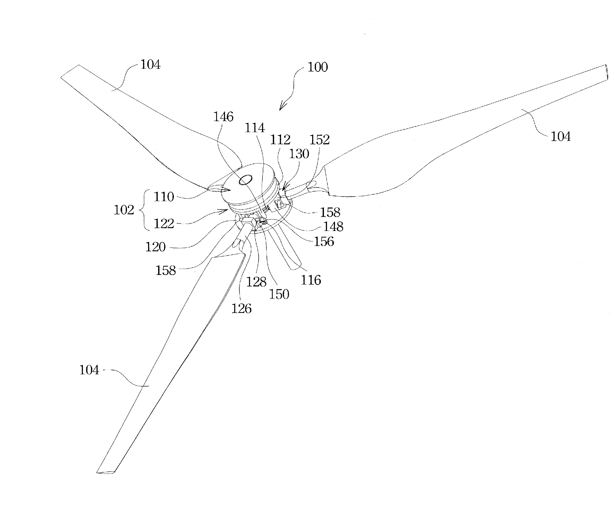
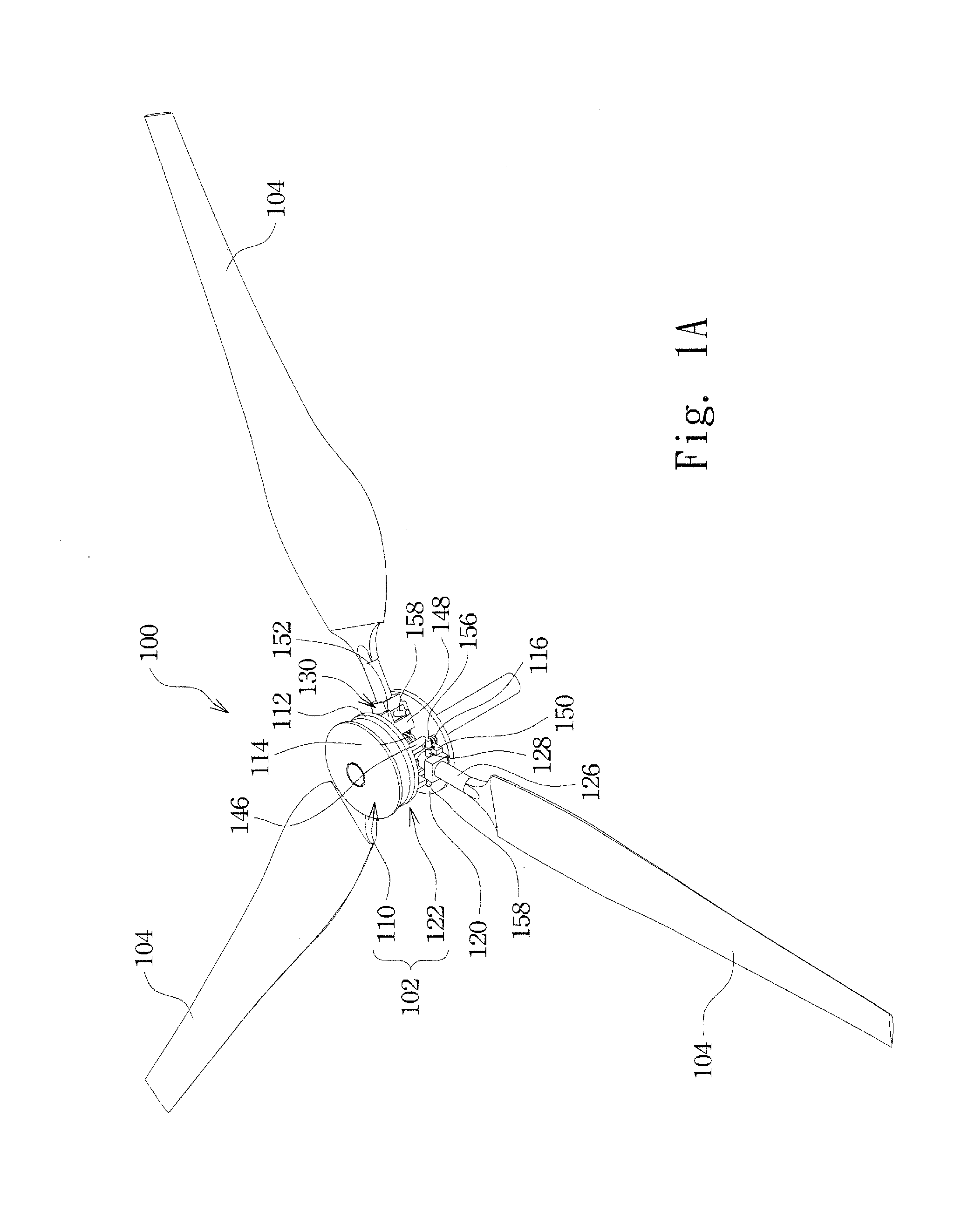
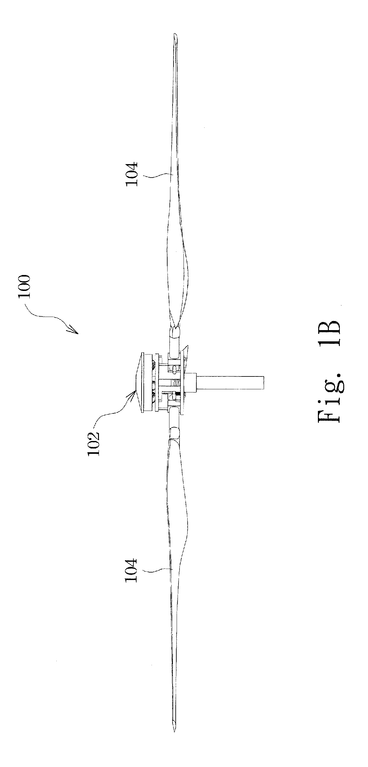
[0007]An objective of the present invention is to provide a blade pitch controlling apparatus and a wind power generator to which the blade pitch controlling apparatus is applied. The blade pitch controlling apparatus comprises a centrifugal device that varies a downward stroke of a blade pitch variable device according to a centrifugal force induced therein to change the setting angle of the blades of the wind power generator, so as to provide the optimum windward attack angle of the blades in the starting acceleration phase, to maintain the operation of steady state rotation of the blades at the attack angle that provides the maximum windward lift force, and to stall the blades in an over-speed condition for reducing the thrust force of the blades.

Problems solved by technology

The exhaustion of the resources of the Earth and the development of technology lead to shortage of energy.
Since the aerodynamic design of the blades only allow for optimization of the input conditions including wind speed and rotational speed, during the operation of the wind power generator, significant challenges that a wind power generator might face are the non-steady-state acceleration phase before it reaches the steady state operation and the protection phase when it takes an over-critical load.
Due to the concerns of volume, weight, economic value, and cost, a small-sized wind power generator is not suitable for such a servo mechanism.
However, the small-sized wind power generator still faces the same problem of non-steady-state acceleration and over-speed protection during the operation thereof.

Method used


Image

  • Blade pitch controlling apparatus and application thereof
  • Blade pitch controlling apparatus and application thereof
  • Blade pitch controlling apparatus and application thereof

Examples


Embodiment Construction

[0030]The following descriptions are exemplary embodiments only, and are not intended to limit the scope, applicability or configuration of the invention in any way. Rather, the following description provides a convenient illustration for implementing exemplary embodiments of the invention. Various changes to the described embodiments may be made in the function and arrangement of the elements described without departing from the scope of the invention as set forth in the appended claims.

[0031]The present invention provides a blade pitch controlling apparatus and an application thereof in a wind power generator for varying the setting angle of blades of the wind power generator in the operation thereof so as to maintain the optimum windward attack angle of the blades in the course of acceleration, maintain the operation of steady state rotation of the blades at the attack angle that provides the maximum windward lift force, and to stall the blades in an over-speed condition for redu...


PUM


Abstract

A blade pitch controlling apparatus and an application thereof are described. The blade pitch controlling apparatus includes a centrifugal device and a blade pitch variable device, and the blade pitch variable device is arranged under the centrifugal device. The blade pitch variable device has a downward stroke that is variable by the centrifugal device according to a centrifugal force induced thereon so as to drive the blade pitch variable device to change the setting angle of the blades of the wind power generator.

Description

(a) TECHNICAL FIELD OF THE INVENTION[0001]The present invention generally relates to a control apparatus of a power generator, and more particularly to a blade pitch controlling apparatus and an application thereof to a wind power generator.(b) DESCRIPTION OF THE PRIOR ART[0002]The exhaustion of the resources of the Earth and the development of technology lead to shortage of energy. Due to such a problem every country in the world is attempting the develop substitute energies, such as solar energy and wind power generation. Among all the substitute energies that are currently available, wind power is a clean and environmentally protective substitute energy.[0003]Generally, a wind power generator uses wind power to drive the rotation of blades, of which the rotational speed might be increased through a speed increasing mechanism for eventually driving a dynamo. In other words, the wind power generation converts wind power into mechanical energy, which is then converted into electrica...

Claims


Application Information

Patent Timeline
IPC IPC(8): F03D7/00
CPCF03D7/0224Y02E10/723F05B2260/77F05B2260/74Y02E10/72
Inventor TSAI, YIFENGHSIAO, FEIBIN
Owner NAT CHENG KUNG UNIV
Learn More