
Video streaming

a video signal and video technology, applied in the field of video signal transmission over telecommunications networks, can solve the problems of packet loss, delay in data packet transmission, and inability to guarantee that data will reach the destination

Active Publication Date: 2010-05-27
BRITISH TELECOMM PLC
View PDF3 Cites 19 Cited by
  • Summary
  • Abstract
  • Description
  • Claims
  • Application Information

AI Technical Summary

Benefits of technology

[0011]It is the aim of embodiments of the present invention to address one or more of the above-stated problems.

Problems solved by technology

When streaming video data over an IP network, there are no guarantees that the data sent will reach its destination.
When the network experiences congestion and other problems, delays will occur to the transmission of the data packets and some packets may even be lost.
Use of such a method is not without problems as delays to segments of the video streams are particularly undesirable.
However, the above congestion scenario may still occur, and two streams each having a different bitrate will still stabilise to roughly the same reduced bitrate when the network is congested.
This may result in some particularly undesirable results where a first stream is initially encoded at a high bitrate, for example a video sequence with high frame activity such as a sports sequence, and a second sequence is encoded at a low bit rate, for example a video sequence with a low frame activity such as a news or drama sequence.
This method of delivery is easier to manage, but is not without its problems.
The second stream transmitted using this fixed bandwidth is thus wasting much of its bandwidth.
However, this increase in quality may not necessarily be significant as perceived by the viewer and may thus be wasted.
Moreover, having this redundant bandwidth is not an efficient use of network resources.
The problems above are heightened when you start considering video sequences that vary in activity during the sequence itself.

Method used


Image

  • Video streaming
  • Video streaming
  • Video streaming

Examples


Embodiment Construction

[0028]The present invention is described herein with reference to particular examples. The invention is not, however, limited to such examples.

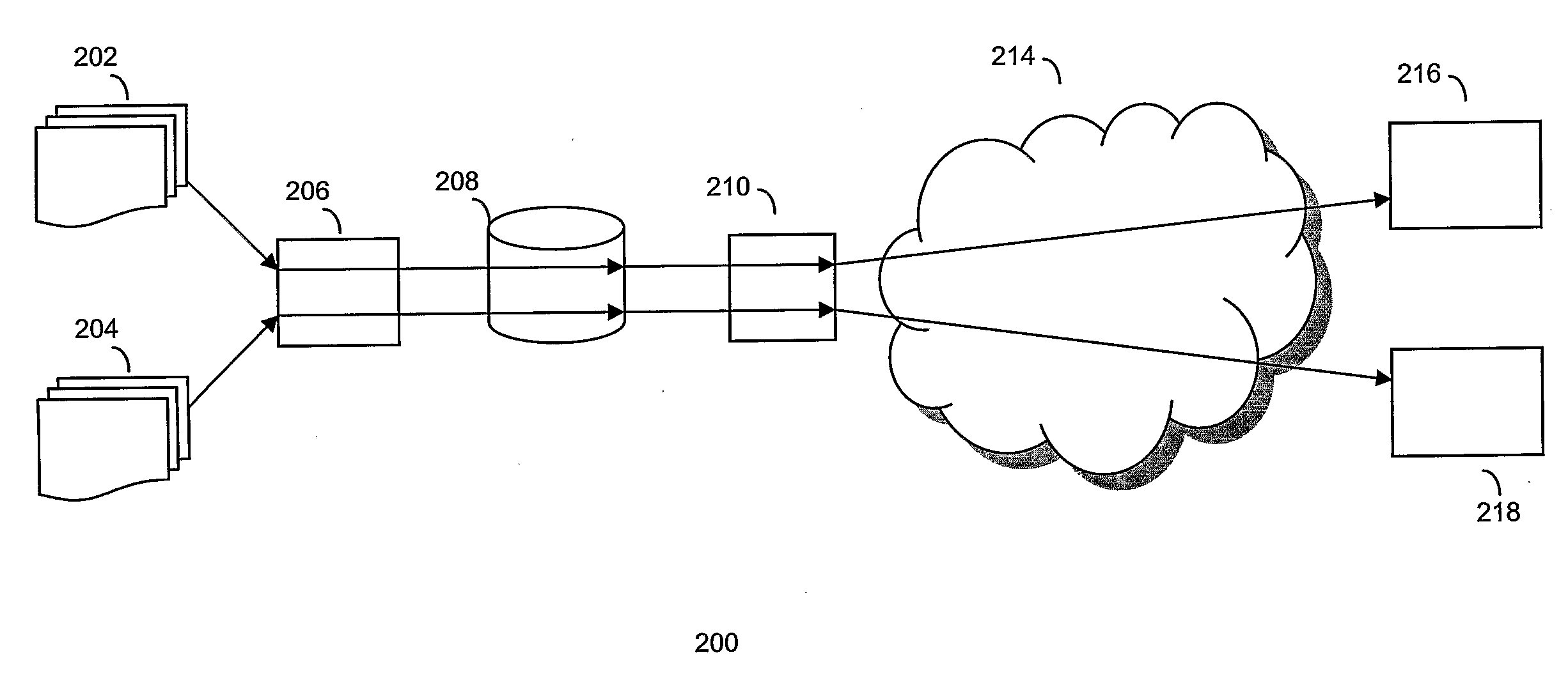
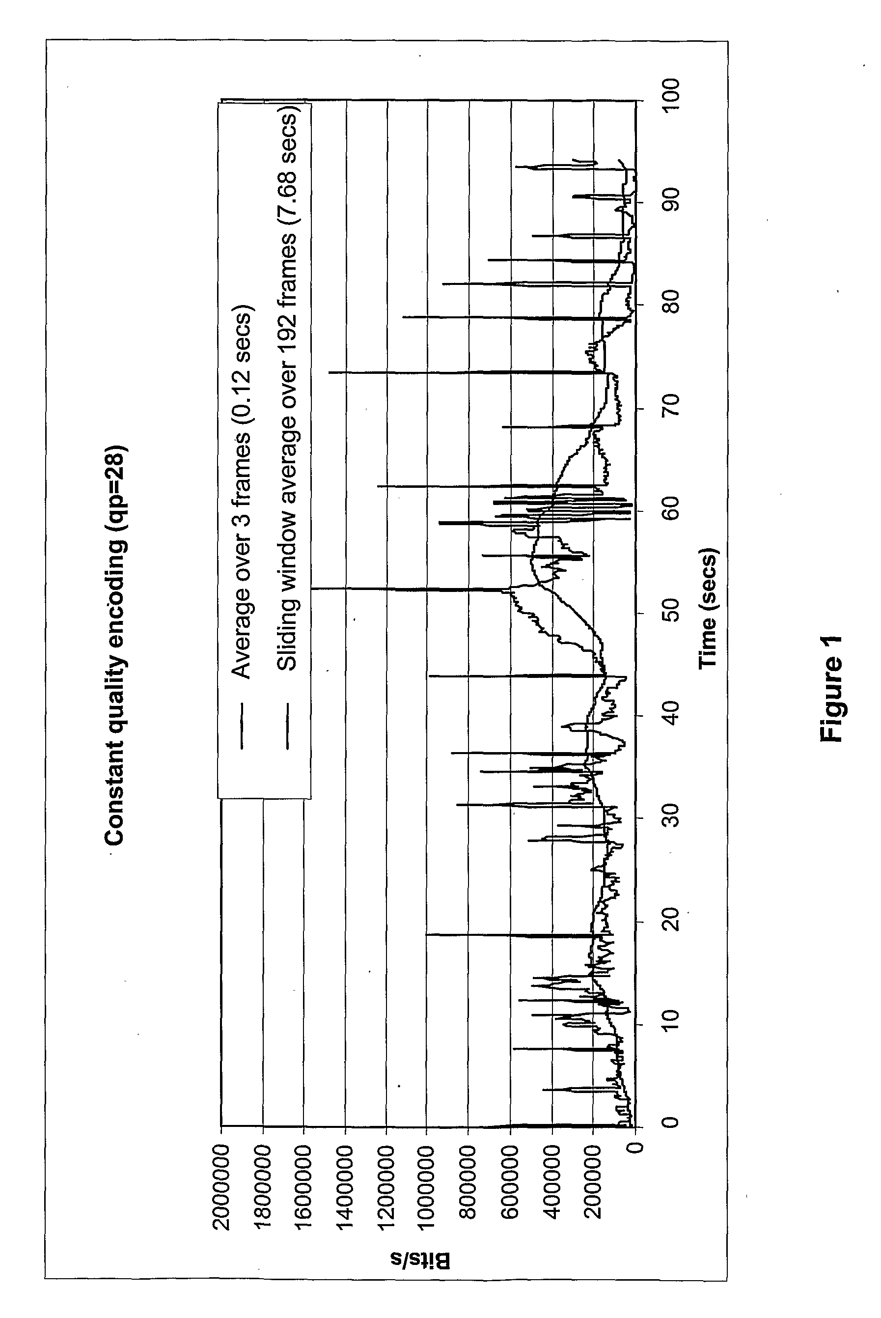
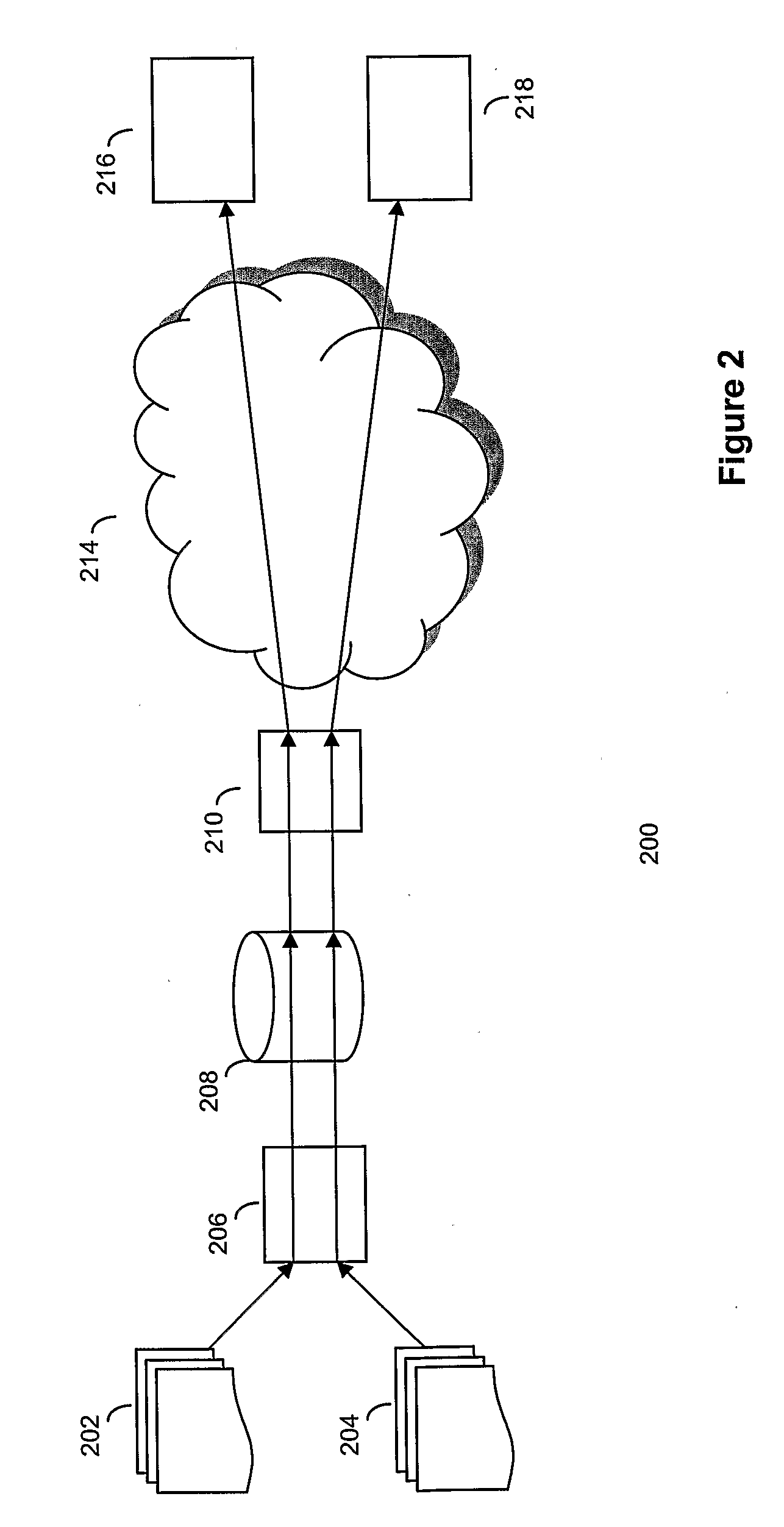
[0029]It is proposed that video streams transmitted over a contended piece of network are encoded at a constant quality rather than at a constant bitrate. If a video sequence is encoded at constant quality, then the bitrate used is likely to vary dramatically. FIG. 1 shows the bitrate over a 90 second video clip encoded at a constant quality level. In this example, the quality level has been determined by setting a quantiser parameter (qp) to 28. The quantiser parameter effectively controls the quality of the encoding—the smaller the quantiser, the better the quality. This clip is typical of many video sequences, with the bitrate varying depending on how complex the scene is at any given moment in time. For example, a sequence of frames where there is much movement or action usually requires a higher bitrate to encode at the same fixed qualit...


PUM


Abstract

The bitrate for any practical video streaming system will vary considerably as a function of the difficulty of encoding the sequence in question. This variation is even more apparent when comparing different video clips of different genres for example where sports clips might require a higher average bitrate and fluctuate more due to the high activity of typical scenes, whereas a news report clip might require a much lower bitrate and be relatively static. As such, to deliver video streams at a constant quality to users sharing a contended network, a constant bandwidth method is not efficient to use across all the streams. The bandwidth allocated to each stream must be allowed to dynamically vary in time in accordance with the precise demands of the video being streamed at that time and also be within any network bandwidth constraints. The present invention defines such a method.

Description

FIELD OF THE INVENTION[0001]The present invention relates to the transmission of video signals over telecommunications networks, and more particularly with a method for controlling the transmission of multiple video streams over a congested network so that each stream receives an equitable share of the bandwidth dependent on the quality of the encoding.BACKGROUND TO THE INVENTION[0002]Transmission of video over data networks, such as the Internet, is commonplace today. To receive such signals, a user can use a suitably configured computer or other receiver such as a “set top box” (STB). STBs have become increasingly popular and many are provided with IP connection allowing content such as video to be streamed or downloaded over the Internet. Television delivered over the Internet, commonly referred to as IPTV, is a good example of this growing service.[0003]When streaming video data over an IP network, there are no guarantees that the data sent will reach its destination. When the n...

Claims


Application Information

Patent Timeline
IPC IPC(8): H04L12/26H04N11/02
CPCH04N21/23106H04N19/164H04N21/23655H04N21/2385H04N21/2402H04N21/26216H04N21/4347H04N21/47202H04N21/64322H04N21/8456H04L65/4084H04L65/602H04L65/80H04N19/115H04N21/2365H04L65/612H04L65/762
Inventor APPLEBY, STEPHEN C.MULROY, PATRICK J.
Owner BRITISH TELECOMM PLC
Learn More