Ground engaging digging tooth

a technology of digging tooth and tooth, which is applied in the direction of soil shifting machine/dredger, construction, etc., can solve the problems of rocky ground to be worked, unable to engage, and difficult digging, etc., and achieve the effect of adding strength and rigidity

Active Publication Date: 2010-05-13
H & L TOOTH
View PDF28 Cites 0 Cited by
  • Summary
  • Abstract
  • Description
  • Claims
  • Application Information

AI Technical Summary

Benefits of technology

[0015]Top, bottom and side surfaces are provided on the tooth. The top and bottom surfaces of the tooth angularly diverge away from each other as each surface extends away from a terminal ends of the tines. Moreover, a cumulative lateral distance between the side surfaces of the tooth at a terminal end of the tines is greater than the lateral distance between the side surfaces of the tooth at the rear end of the tooth such that the bucket edge and retainer apparatus are beneficially provided with additional wear protection.
[0016]In one form, the digging tooth is provided with a secondary lock to inhibit inadvertent axial separation of the retainer apparatus relative to the adapter or tooth. Preferably, the top surface of the digging tooth includes a raised and longitudinally elongated rib for adding strength and rigidity to the central tine. In another form, the bottom surface of the digging tooth includes a raised and longitudinally elongated rib for adding strength and rigidity to the central tine.

Problems solved by technology

During operation, poor ground and soil conditions are frequently encountered making digging very difficult.
Often, the ground to be worked is rocky, frozen or simply very well packed and dense, such as compacted adobe, decomposed granite roads, and etc.
Since a number of the cutting edges on the teeth contact the ground at the same time, penetration into hard ground conditions can be difficult and very limited.
While often effective, a single tine offers a relatively narrow penetration zone.
A single tine digging tooth also tends to wear rapidly and requires frequent replacement.
Wear of the tines on the tooth, however, remains a problem.
Moreover, and unless the points or tines on the digging tooth are adequately spaced apart from each other, the space therebetween can and frequently does entrap rocks therebetween whereby furthermore reducing the efficiency of the digging tooth.
Also, and depending upon their placement along the front edge of the bucket, the two tines on the digging tooth can have different wear patterns associated with each tine which can result in an increase in the amount of “throw away” of a worn tooth.

Method used


Image

  • Ground engaging digging tooth
  • Ground engaging digging tooth
  • Ground engaging digging tooth

Examples


Embodiment Construction

[0030]While the present invention disclosure is susceptible of embodiment in multiple forms, there is shown in the drawings and will hereinafter be described a preferred embodiment of the invention disclosure, with the understanding the present disclosure is to be considered as setting forth an exemplification which is not intended to limit the invention disclosure to the specific embodiment illustrated and described.

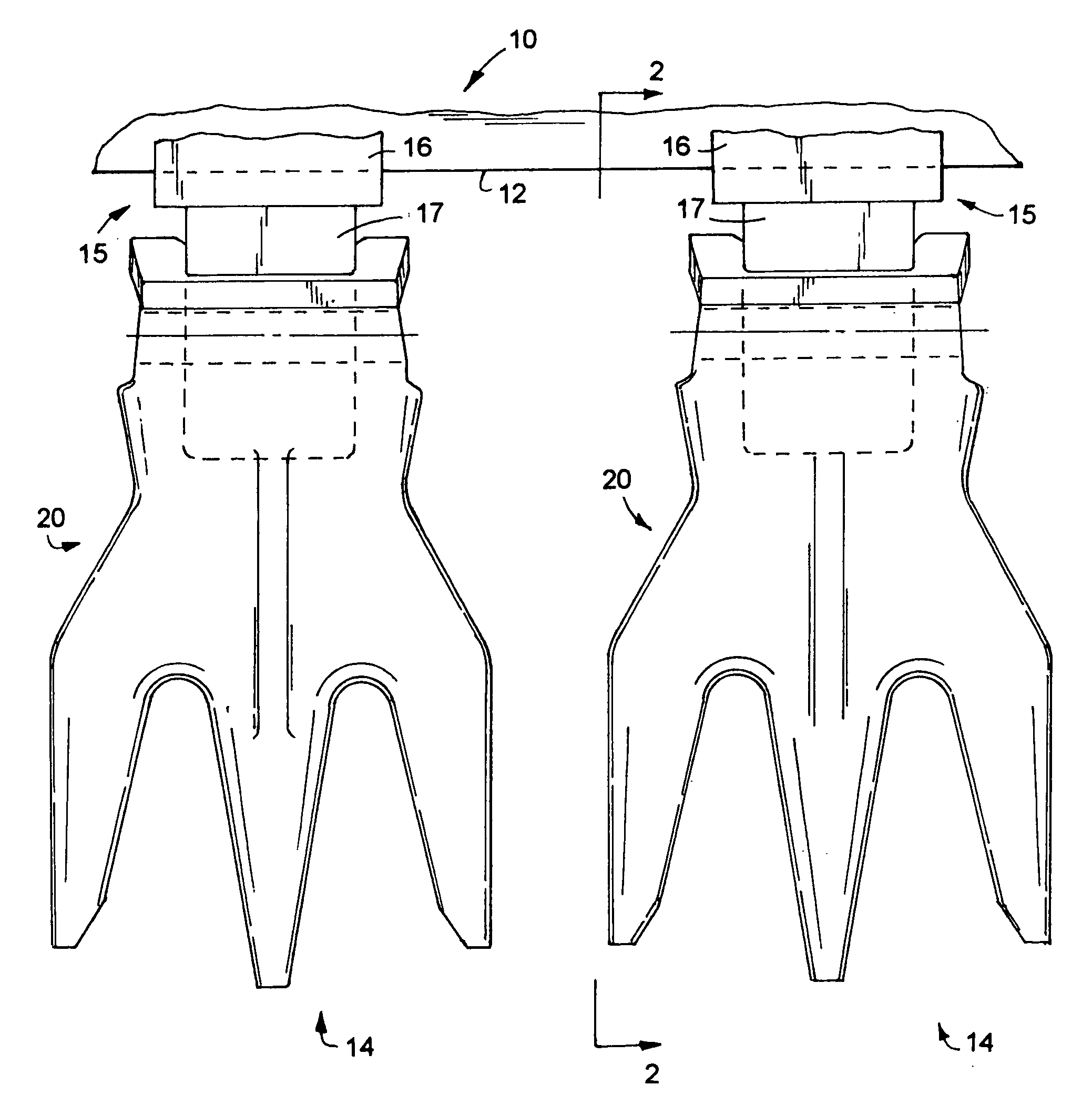
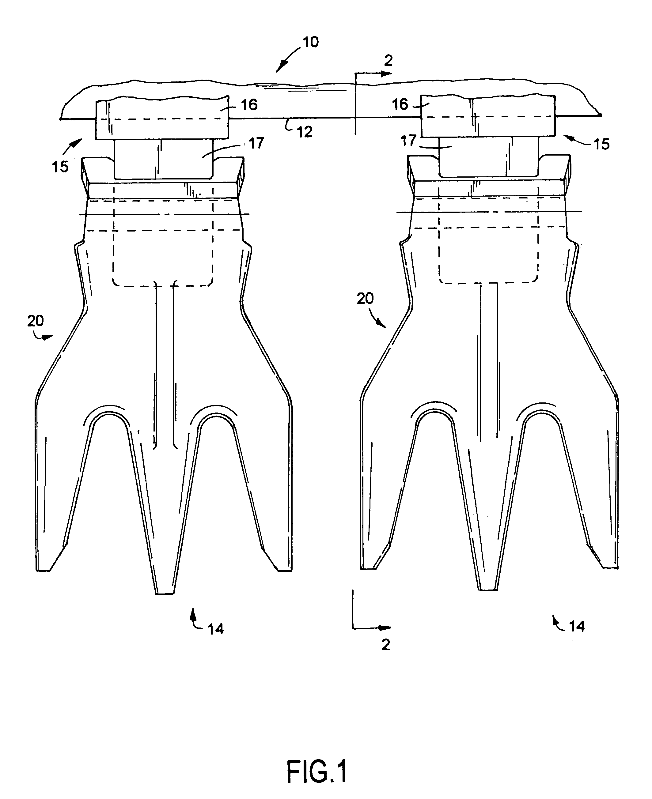
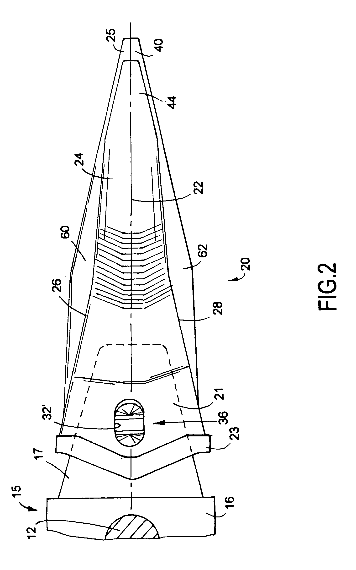
[0031]Referring now to the drawings, wherein like reference numerals indicate like parts throughout the several views, there is shown in FIG. 1 a fragmentary plan view of a bucket for a backhoe, power shovel, or related ground working implement or equipment generally identified by reference numeral 10. Such ground working equipment 10 is typically provided with a transverse extending lip or leading edge 12 and has a plurality of multipiece digging tooth assemblies 14 arranged in laterally spaced relation relative to each other along and extending forward from such lip o...


PUM


Abstract

A one-piece digging tooth having a socket opening to a rear end of the tooth for receiving and accommodating at least a lengthwise portion of a nose portion of an adapter extending forward from earth working equipment. The digging tooth has a top surface and a bottom surface which angularly diverge from each other between a forward end and the rear end of the tooth and two side surfaces. The tooth further includes a longitudinally elongated and centrally disposed tine with another longitudinally elongated tine outwardly cantilevered from and disposed to opposite lateral sides of and extending generally parallel to the central tine. To enhance their penetration capability, a width and thickness of all the tines constantly diminishes as the tines longitudinally extend toward the forward edge of the tooth. Opposed side surfaces on each tine are separated from each other by a longitudinally cleft whereby providing the digging tooth with at least two channels for directing materials, worked free by the tines, rearwardly toward and into the earth working equipment.

Description

FIELD OF THE INVENTION DISCLOSURE[0001]The present invention disclosure generally relates to ground engaging tools and, more particularly, to a ground engaging digging tooth.BACKGROUND OF THE INVENTION DISCLOSURE[0002]Many of today's ground engaging equipment i.e., backhoes, power shovels, and related devices includes a bucket having a transversely extending leading edge. During operation, poor ground and soil conditions are frequently encountered making digging very difficult. Often, the ground to be worked is rocky, frozen or simply very well packed and dense, such as compacted adobe, decomposed granite roads, and etc.[0003]To facilitate ground penetration, s series of laterally spaced digging tooth assemblies extend forward from the leading edge of the bucket. Some digging tooth assemblies embody a two-piece design including an adapter connected to and extending forward from the leading edge of the bucket and a replaceable digging tooth mounted on and carried by the adapter. Some...

Claims


Application Information

Patent Timeline
Patent Type & Authority Applications(United States)
IPC IPC(8): E02F9/28
CPCE02F9/2858
Inventor LAUNDER, BRIAN L.CLENDENNING, CHARLESDRAKE, RUSSELL N.
Owner H & L TOOTH
Why Eureka
Try Eureka