Eureka AIR delivers breakthrough ideas for toughest innovation challenges, trusted by R&D personnel around the world.

Clutch characteristic adaption method for automatic dual clutch transmission

Active Publication Date: 2010-05-06
ZF FRIEDRICHSHAFEN AG
View PDF3 Cites 41 Cited by
  • Summary
  • Abstract
  • Description
  • Claims
  • Application Information

AI Technical Summary

Benefits of technology

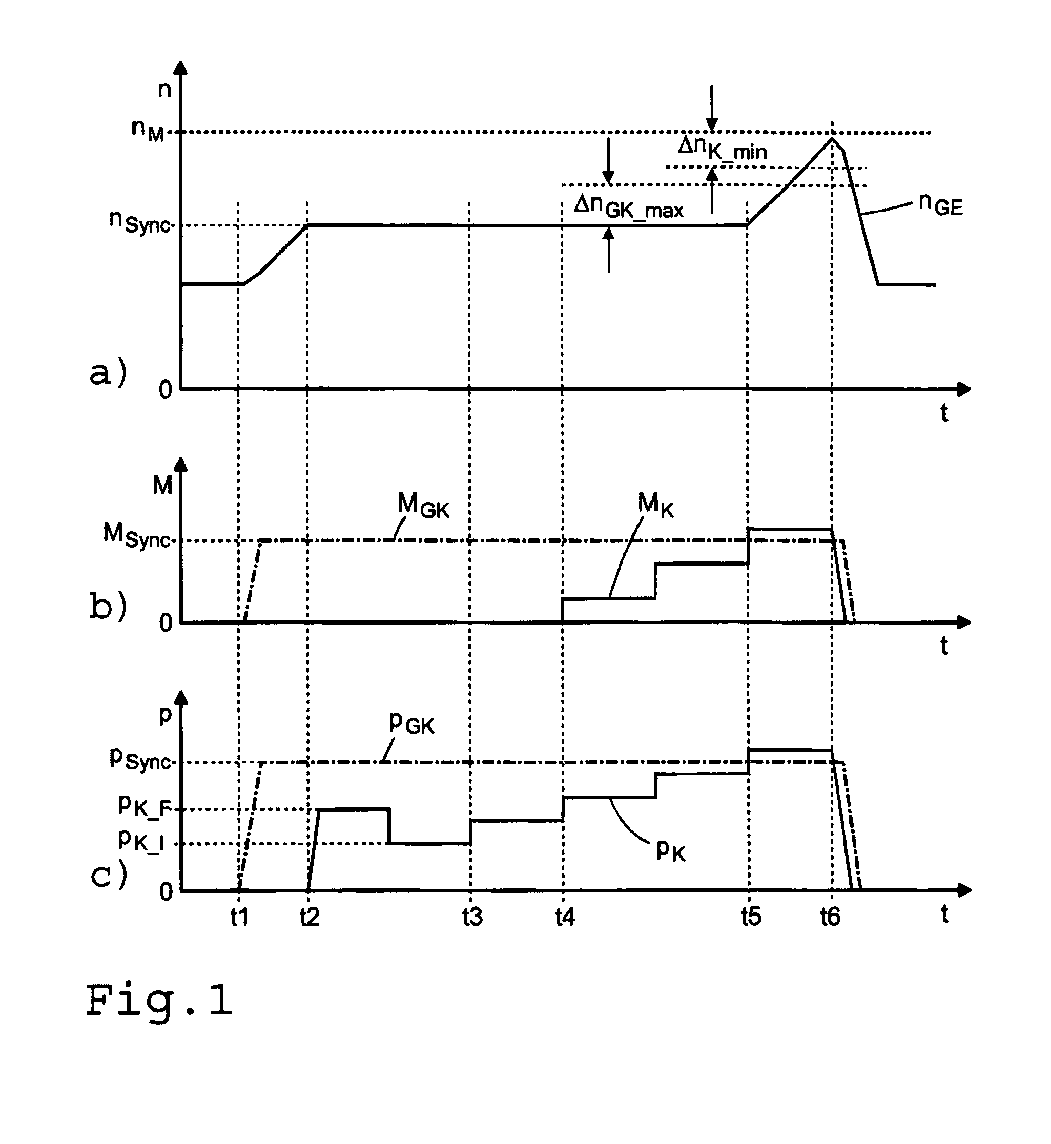
[0027]Since the clutch torque of the friction clutch exceeds the synchronous torque at the gear clutch within the sequence of the method, a relatively high synchronous torque can be set on the gear clutch without the danger appearing of interconnection of the gear clutch, namely unintentional engagement of the gear in question. Accordingly, the synchronous torque is kept comparatively small so that it is not noticeable to the driver of the vehicle, when the clutch torque of the friction clutch exceeds the synchronous torque. Furthermore the synchronous torque is determined in a load-free manner and it remains constant during the determination of the touch point. In addition, the synchronous position is constantly monitored for safety sake. As soon as this synchronous position is exceeded, the procedure is stopped. That prevents the clutch torque from further increasing which would then result in a noticeable delay of the vehicle. In particular, a higher regulating force level can be preset in the gear regulator and the clutch regulator or a higher torque level in the gear clutch and the friction clutch compared to the method known from WO 2004 / 076225 A1, owing to which there advantageously is a higher accuracy in the determination of the touch point of the friction clutch.
[0031]In an actively engagable construction of the friction clutch, for example as a multiple disc clutch, and a construction of the associated clutch regulator as a hydraulic or pneumatic adjusting cylinder, it is advantageously provided for the acceleration of the procedural sequence that the clutch regulator is first filled with a filling pressure and a low initializing pressure before the engagement of the friction clutch. The friction elements of the friction clutch in question are thereby pre-stressed in the direction of the touch point so that the following engagement procedure and the reaching of the touch point occur faster.
[0032]A determination of the current synchronous point of the applicable gear clutch is appropriately performed before the determination of a current touch point of the friction clutch in order to increase accuracy.
[0035]It is likewise advantageous while driving, if the synchronous point of the gear clutch of the next highest or lowest gear in relation to the gear engaged in the other sub-gearbox is started. Because of the relatively small rotational speed difference at the gear clutch in question, the wear on the associated synchronization caused by the method is reduced. Furthermore, in a looming shift change the gear in question will form the target gear with a high degree of probability so that the gear can, if applicable, be immediately fully engaged at the end of the procedural sequence.
[0037]The engagement of the friction clutch of the load-free sub-gearbox preferably occurs in a gradual progression of the regulating parameters of the mentioned clutch regulator with an applicable stage offset and an applicable stop duration per engagement stage. The gradual engagement of the friction clutch requires, to be sure, a certain control effort, but it has the advantage that after each engagement step the effect is then awaited, i.e., a possible cancellation of the synchronization at the gear clutch in question before the next engagement step follows. Higher accuracy hereby results in the determination of the touch point compared to a continuous engagement.
[0041]According to a second variant of the method of the invention, the engagement of the friction clutch of the load-free sub-gearbox can, however, occur in a ramp-like progression of the regulating parameter of the respective clutch regulator with an applicable regulating gradient. Opposing the advantage of simple controllability of the constant engagement process there stands the disadvantage of reduced precision in the determination of the touch point which results from the time delay between exceeding the synchronous torque of the gear clutch by the clutch torque of the friction clutch and sensor-detected cessation of synchronization at the gear clutch.

Problems solved by technology

Furthermore, there can be deviations with respect to the touch points within a series production of friction clutches of the same design because of manufacturing tolerances.
The known procedure indeed includes a zero point adjustment of the clutch regulator; nevertheless, the determination or adaptation of the touch point is only possible when a vehicle is stopped and idling control of the drive motor is activated, and is thus relatively seldom possible.
In addition, the known procedure is critical for safety, since too great an engagement of the friction clutch, i.e., too high a clutch torque, can result in an unintentional rolling of the vehicle, whereas too small an engagement of the friction clutch, and likewise a too small clutch torque, can result in a relatively too small increase of the motor torque that can not be distinguished from other impairments of the idling revolutions of the drive motor.
The known method can be used both with a stopped vehicle and when driving, but features a relatively high degree of inexactness in the determination of the touch point because of multiple influence parameters.
This known method is accordingly relatively time-consuming and disadvantageously requires a high storage and calculation capacity.
The set clutch torque of the friction clutch must also be comparatively low, since otherwise it can not be overcome by the temporarily set synchronous torque of the synchronization of the gear clutch or there is the danger of an unintentional complete engagement of the gear clutch.

Method used


Image

  • Clutch characteristic adaption method for automatic dual clutch transmission
  • Clutch characteristic adaption method for automatic dual clutch transmission
  • Clutch characteristic adaption method for automatic dual clutch transmission

Examples


Embodiment Construction

[0057]A known dual-clutch transmission 1 designed here, for example, as a six gear transmission in which the method of the invention for clutch characteristic curve adaptation can be used is depicted in a simplified manner in FIG. 4. The method of the invention, however, also functions in another dual-clutch transmission, for example in a dual-clutch transmission with seven or eight gears. The dual-clutch transmission 1 features a longer first input shaft 3, a shorter second input shaft 4 designed as a hollow shaft and placed coaxially above the first input shaft 3, a countershaft 5 positioned parallel to the two input shafts 3, 4, as well as an output shaft 6 positioned coaxially and axially adjacent to the first input shaft 3.

[0058]The first input shaft 3 is connectable by the engagement of respectively one associated gear clutch via the gear wheel sets of a first forward gear G1 and a third forward gear G3 with the countershaft 5, which is in a power-connection with the output sh...


PUM


Abstract

A method for clutch characteristic curve adaptation of an automatic dual-clutch transmission which comprises two sub-gearboxes each with an input shaft connected, via a friction clutch, to the drive shaft of a motor and several gears that are shifted via a friction-synchronized gear clutch. A value of the current touch point of the friction clutch can be determined with the motor running and the gears disengaged in a load-free sub-gearbox. The method includes the steps of starting synchronization of a gear clutch with a defined force of a regulator. Waiting until the gear clutch is synchronized. Engaging the friction clutch of the until the gear clutch is synchronizes. Determination the current touch point from the current synchronous torque of the gear clutch and the current regulating parameter of the associated clutch regulator. Then, adapting the clutch characteristic curve of the friction clutch in view of the current touch point.

Description

[0001]This application claims priority from German patent application serial no. 10 2008 043 384.5 filed Nov. 3, 2008.FIELD OF THE INVENTION[0002]The invention involves a method for clutch characteristic curve adaptation of an automatic dual-clutch transmission which comprises two sub-gearboxes each with an input shaft connected, via a friction clutch, to the drive shaft of a drive motor and several gears shiftable via a friction-synchronized gear clutch, whereby a current value of the touch point of the associated friction clutch can be determined in conjunction with partial engagement of the friction clutch in question and the acquisition of the relevant operating parameters with a running motor and disengaged gears in a load-free sub-gearbox.BACKGROUND OF THE INVENTION[0003]Motor vehicles are increasingly equipped with automatic clutches which can be designed, like in the manner of construction of a single or multiple-disc dry clutch equipped with a pressure spring, as a passivel...

Claims


Application Information

Patent Timeline
IPC IPC(8): G06F17/00
CPCF16D48/066F16D2500/1026F16D2500/1086F16D2500/3024F16D2500/30426F16D2500/308F16D2500/30816F16D2500/50272F16D2500/70605F16H61/0403F16H61/688F16H2306/48F16H2342/042
Inventor TERWART, MARKUSBUHNER, MARIOLOCHER, KARLBADER, MARTIN-JOACHIMZUBER, DIETMARMOSELER, OLAF
Owner ZF FRIEDRICHSHAFEN AG
Why Eureka
Eureka Blog
Learn More