Optical glass, preform for press forming, optical element, and processes for producing these
a technology of optical glass and fluorophosphate, which is applied in the field of fluorophosphate optical glass, can solve the problems of optically non-uniform portion called striae, no fundamental solution to prevent the volatilization of the above glass components, etc., and achieve the effect of suppressing the volatilization of a glass component and the variation of quality
- Summary
- Abstract
- Description
- Claims
- Application Information
AI Technical Summary
Benefits of technology
Problems solved by technology
Method used
Image
Examples
example 2
Production Examples of Press-Molding Preforms
[0357]Preforms were produced from the optical glasses Nos. 1 to 38 shown in Tables 1-1 to 1-8 in the following manner. A molten glass was caused to flow at a constant flow rate out of a pipe made of a platinum alloy that was temperature-adjusted to a temperature range in which the molten glass could be caused to stably flow out without devitrification of the glass. And, molten glass gobs were separated by a method in which the glass gob was allowed to drop or a method in which the forward end of the molten glass was supported with a support and then the support was rapidly moved down to separate the glass gob. It should be understood that each of the thus-obtained molten glass gobs had the weight obtained by adding the weight of removal amount to the weight of one preform intended.
[0358]Then, the thus-obtained molten glass gobs were received with receiving molds with an ejection port in the bottom portion thereof each, and press-molding p...
example 3
Production Example of Optical Elements
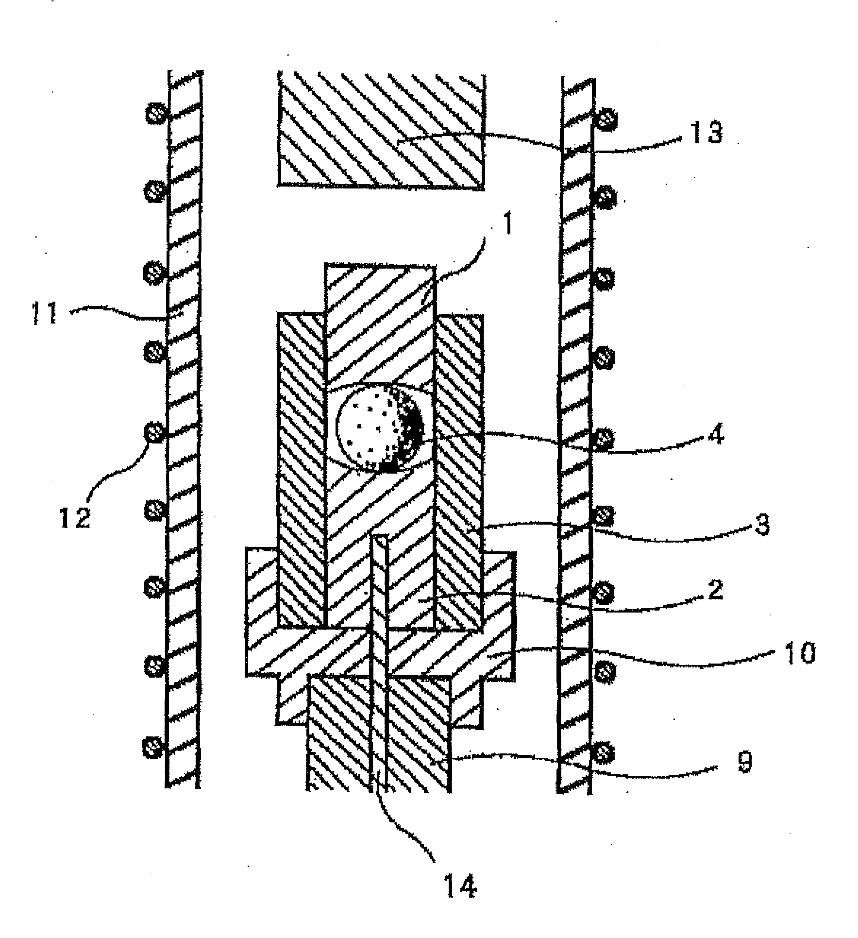
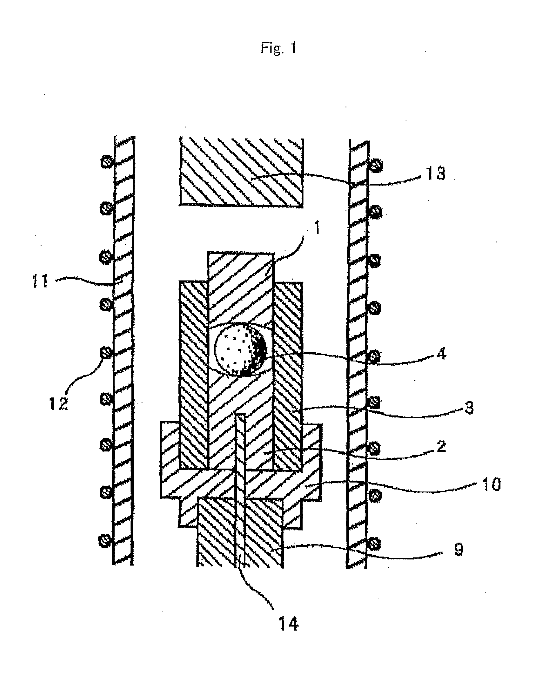
[0362]Each of the above-obtained preforms was precision press-molded with a press apparatus shown in FIG. 1 to give aspherical lenses.
[0363]That is, there was provided a press mold having an upper mold member 1, a lower mold member 2 and a sleeve 3, and a preform was placed between the lower mold member 2 and the upper mold member 1. Then, a nitrogen atmosphere was introduced into a quartz tube 11, and a heater 12 is electrically powered to heat the inside of the quartz tube 11. The temperature inside the press mold was set at a temperature at which the glass to be molded exhibited a viscosity of 108 to 1019 dPa·s, and while this temperature was maintained, a press rod 13 was moved downward to press the upper mold member 1, and the preform set in the mold was thereby pressed. The pressure of the press was set at 8 MPa, and the pressing time period was set for 30 seconds. After the pressing, the pressure of the press was removed, and the glass mo...
example 4
Production Example of Optical Element Blank
[0369]Optical element blanks were produced from the optical glasses Nos. 1 to 38 shown in Tables 1-1 to 1-8 in the following manner. A molten glass was caused to flow at a constant flow rate out of a pipe made of a platinum alloy that was temperature-adjusted to a temperature range in which the molten glass could be caused to stably flow out without devitrification of the glass, and the molten glass was fed on the molding surface of a lower mold member constituting a press mold. Incidentally, prior to the feeding of the molten glass, a mold release agent in the form of a powder such as a boron nitride powder is uniformly applied to the molding surface of the lower mold member.
[0370]Then, the molten glass that is flowing out is cut with a cutting blade called shears, to obtain a molten glass gob on the molding surface of the lower mold member.
[0371]Then, the lower mold member with the molten glass gob on it is introduced into a position wher...
PUM
| Property | Measurement | Unit |
|---|---|---|
| Fraction | aaaaa | aaaaa |
| Fraction | aaaaa | aaaaa |
| Fraction | aaaaa | aaaaa |
Abstract
Description
Claims
Application Information
 - R&D
- Intellectual Property
- Life Sciences
- Materials
- Tech Scout
- Unparalleled Data Quality
- Higher Quality Content
- 60% Fewer Hallucinations
Browse by: Latest US Patents, China's latest patents, Technical Efficacy Thesaurus, Application Domain, Technology Topic, Popular Technical Reports.
© 2025 PatSnap. All rights reserved.Legal|Privacy policy|Modern Slavery Act Transparency Statement|Sitemap|About US| Contact US: help@patsnap.com


