
Systems and Methods for High-Throughput Turbidity Measurements

a high-throughput turbidity and measurement system technology, applied in the field of systems and methods for high-throughput turbidity measurement, can solve the problem that the type of experiment can be substantially time-consuming

Inactive Publication Date: 2010-05-06
DOW GLOBAL TECH LLC
View PDF7 Cites 19 Cited by
  • Summary
  • Abstract
  • Description
  • Claims
  • Application Information

AI Technical Summary

Problems solved by technology

In practice, however, this type of experiment can be substantially time consuming.

Method used


Image

  • Systems and Methods for High-Throughput Turbidity Measurements
  • Systems and Methods for High-Throughput Turbidity Measurements
  • Systems and Methods for High-Throughput Turbidity Measurements

Examples


Embodiment Construction

1. Overview

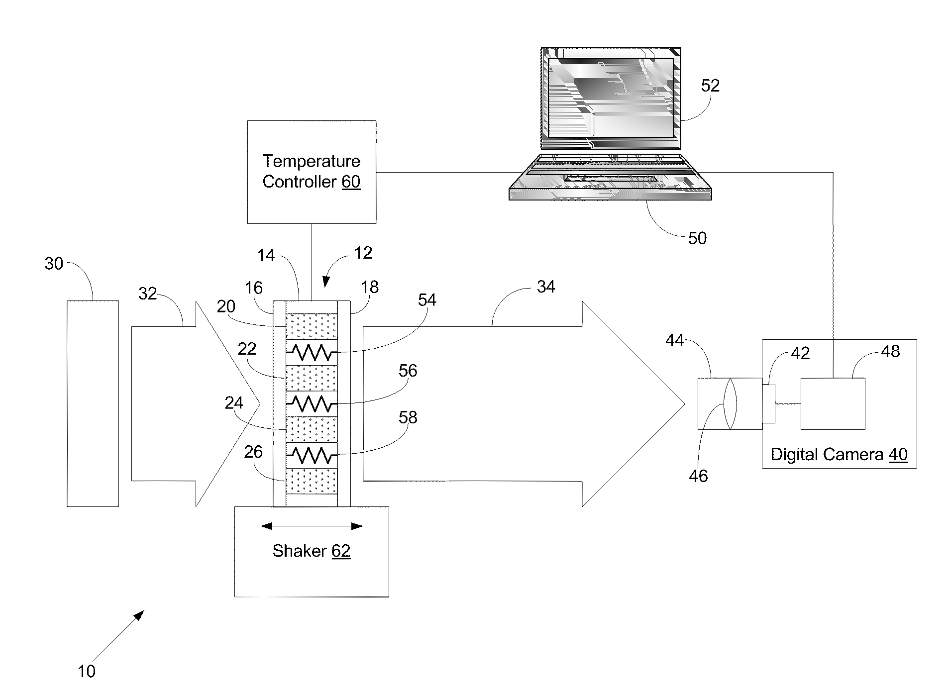
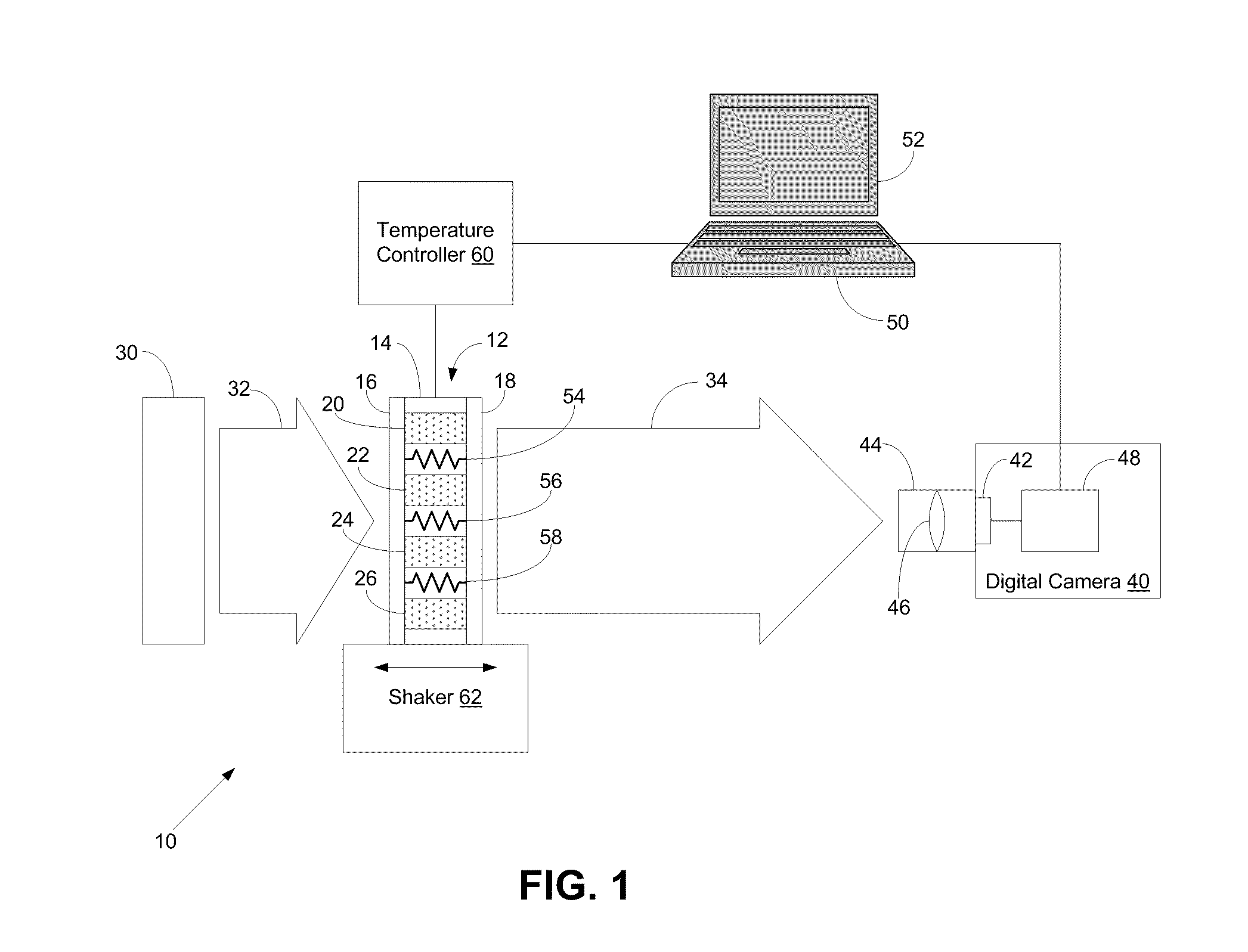
[0018]To facilitate turbidity measurements of a plurality of samples in a high-throughput manner, a light source may be arranged to illuminate all of the samples in a sample assembly, and a light detection system may be arranged to obtain an exposure that includes light from the light source transmitted through each of the samples. The sample assembly may include a plurality of distinct locations for receiving samples. For example, the sample assembly may include a plurality of containers, such as wells, vials, or cuvettes. The containers may be arranged in an array and may be optically transparent.

[0019]The light source may be configured to uniformly illuminate one side of the sample assembly. For example, the light source might include a diffuse light panel. A light detection system, such as a digital camera, may be arranged on the other side of the sample assembly so that its field of view encompasses all of the samples in the sample assembly. While the sample assembly...


PUM

PropertyMeasurementUnit
turbidityaaaaaaaaaa
temperatureaaaaaaaaaa
optical path lengthaaaaaaaaaa

Abstract

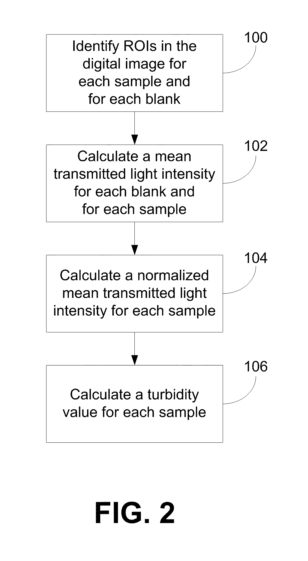
A turbidity measurement system includes a sample assembly that contains a plurality of samples, a light source that illuminates the sample assembly, and a light detection system that includes a two-dimensional light-sensitive array. The light-sensitive array is simultaneously exposed to light transmitted through each of the samples in the sample assembly. The exposure is analyzed to determine a mean transmitted light intensity for each sample and to calculate a turbidity value for each sample based on its mean transmitted light intensity. Multiple exposures may be taken during a measurement period so as to obtain time-resolved turbidity measurements of the samples. The temperature of the samples may be varied during the measurement period so as to measure turbidity as a function of temperature.

Description

CROSS-REFERENCE TO RELATED APPLICATIONS[0001]This application is a continuation-in-part of International Patent Application No. PCT / US2008 / 059575, filed Apr. 7, 2008, which claims the benefit of U.S. Provisional Patent Application No. 60 / 916,878, filed May 9, 2007. The foregoing applications are incorporated herein by reference.BACKGROUND[0002]1. Field of the Invention[0003]The present invention relates to systems and methods for determining at least one parameter in each of a plurality of samples that are illuminated by a light source, for example, to facilitate high-throughput turbidity measurements.[0004]2. Description of Related Art[0005]Turbidimetry is the measurement of decreased intensity of incident light that is caused by scattering in an inhomogeneous system. The scattering could be caused, for example, by solid particles suspended in a liquid or by a mixture of different liquid phases that have different indices of refraction.[0006]The “turbidity” of the inhomogeneous sys...

Claims


Application Information

Patent Timeline
Patent Type & Authority Applications(United States)
IPC IPC(8): G06K9/00G01N21/59H04N5/222
CPCG01N21/534G01N21/59G01N2201/1211G01N2201/0461G01N2021/5957
Inventor LEUGERS, MARY ANNEKUO, TZU-CHIMECCA, JODI MILHAUPTMOHLER, CAROL ELAINE
Owner DOW GLOBAL TECH LLC
Learn More