
Pressure sensor

a technology of pressure sensor and pressure sensor, which is applied in the direction of optical radiation measurement, force measurement by measuring optical property variation, instruments, etc., can solve the problems of mode hopping and hysteresis, and severe difficulties

Inactive Publication Date: 2010-05-06
ABB RES LTD
View PDF35 Cites 11 Cited by
  • Summary
  • Abstract
  • Description
  • Claims
  • Application Information

AI Technical Summary

Benefits of technology

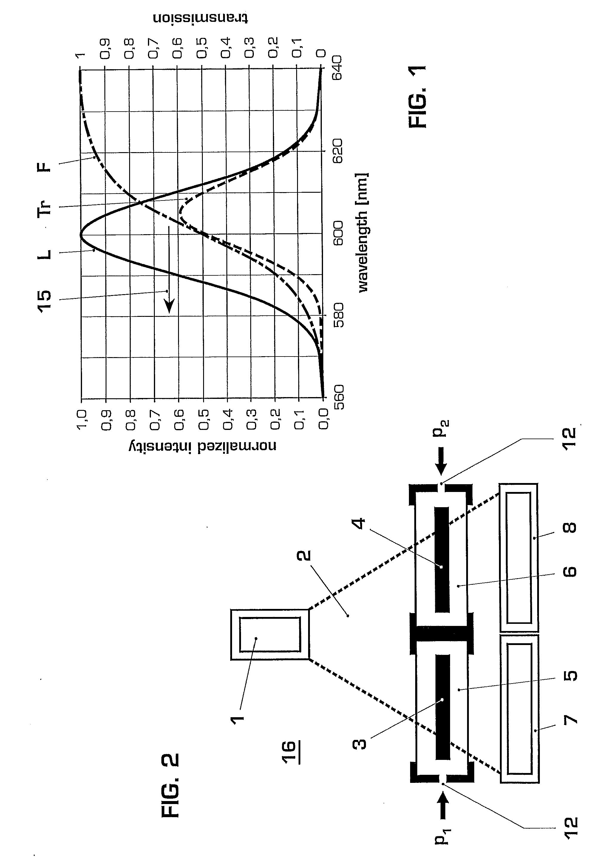
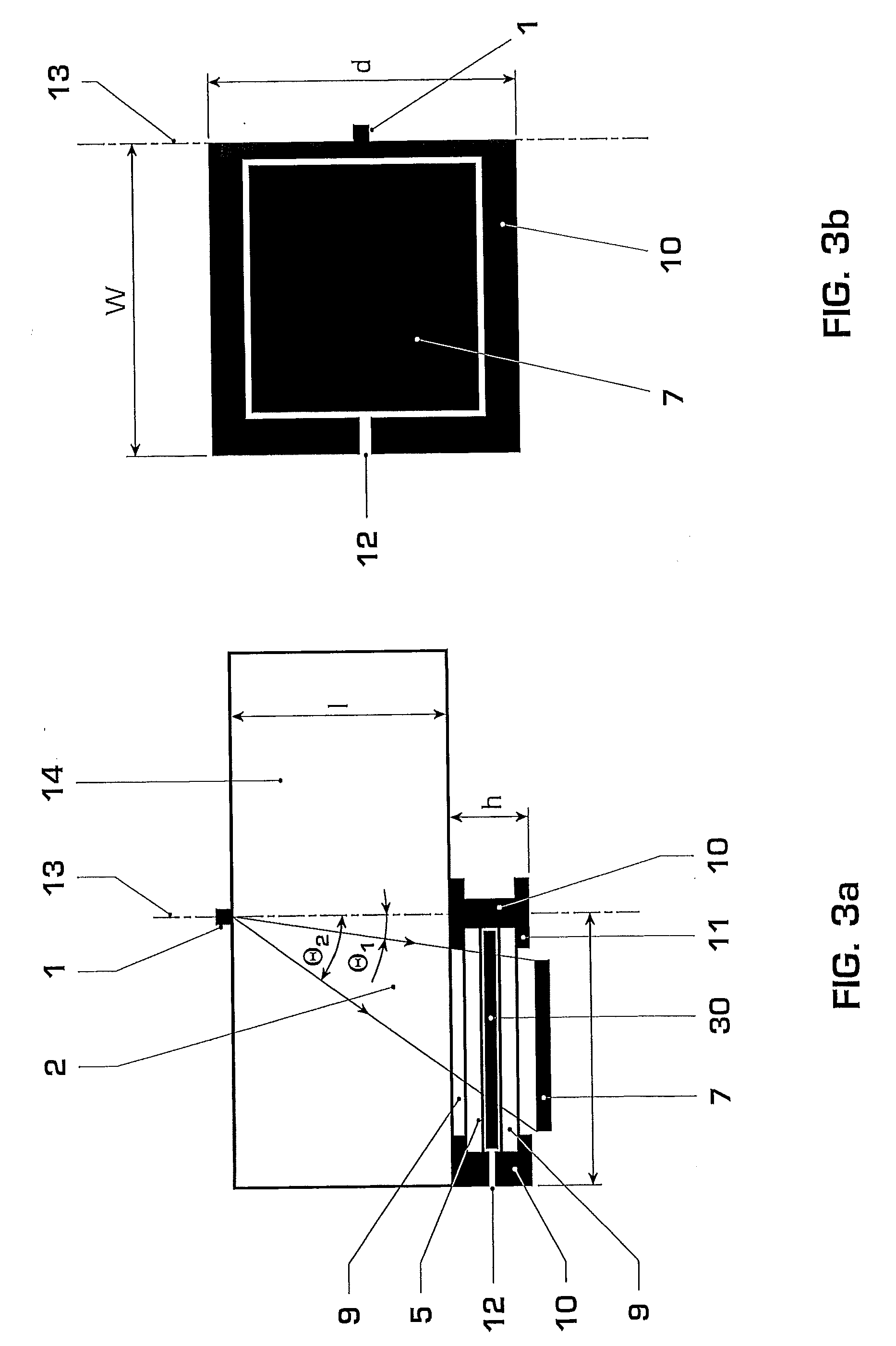
"The patent describes a pressure sensor that uses two pressure sensing elements and two detectors to measure pressure differences between two chambers. The sensing elements are positioned close to each other and are irradiated by a common light source. The detectors measure the light transmitted through the sensing elements, which depends on pressure. By analyzing the output of the detectors, the sensor can evaluate the pressure difference between the two chambers. This technology allows for more accurate and precise pressure measurement in a compact design."

Problems solved by technology

However this can result in severe difficulties, such as thermal stabilization and temperature cross-talk effects.
For the latter, problems can be related to mode hopping and hysteresis.

Method used


Image

  • Pressure sensor
  • Pressure sensor
  • Pressure sensor

Examples


Embodiment Construction

[0018]A pressure sensor assembly is disclosed in which, for example, at least some of the deficiencies of known assemblies can be reduced, if not eliminated. An exemplary pressure sensor is disclosed with at least one semiconductor-based pressure sensing element, pressure induced changes in optical properties of the sensing element being read out by illumination with at least one light source. A differential pressure sensor can be realized with, for example, high accuracy and low errors caused by temperature effects.

[0019]An exemplary pressure sensor as disclosed herein includes at least two semiconductor-based pressure sensing elements located in individual pressure chambers, which sensing elements can be located essentially adjacent to each other and which sensing elements can be irradiated with a light source, such as a common (i.e., the same) light source, wherein light transmitted through the sensing elements can be detected using at least two corresponding detectors, and where...


PUM


Abstract

A pressure sensor is disclosed with at least one pressure sensing element, the pressure induced changes in the optical properties of which are evaluated by illumination with at least one light source. The pressure sensor can include at least two semiconductor-based pressure sensing elements located in individual pressure chambers, which sensing elements are located essentially adjacent to each other. The sensing elements can be irradiated with the same light source, wherein the light transmitted through the sensing elements is detected using at least two corresponding detectors, and wherein the differential pressure in the two pressure chambers is evaluated based on the output of these detectors.

Description

RELATED APPLICATION[0001]This application claims priority as a continuation application under 35 U.S.C. §120 to PCT / EP2007 / 057193 filed as an International Application on Jul. 12, 2007 designating the U.S., the entire content of which is hereby incorporated by reference in its entirety.FIELD[0002]The present disclosure pertains to the field of pressure sensing elements which are based on pressure sensor units wherein, for example, the pressure induced changes in the optical properties of which are read out by illumination with a light source.BACKGROUND INFORMATION[0003]From patent literature and from other technical publications it is known to utilize photoluminescence or absorption characteristics in semiconductor materials for measurement of parameters, such as temperature and pressure.[0004]It has been proposed to use the shift of the absorption edge of bulk GaAs for pressure sensing. However this can result in severe difficulties, such as thermal stabilization and temperature cr...

Claims


Application Information

Patent Timeline
Patent Type & Authority Applications(United States)
IPC IPC(8): G01L7/00G01J1/00
CPCG01L1/24G01L11/02
Inventor KRAMER, AXELKASSUBEK, FRANKBOHNERT, KLAUSBRAENDLE, HUBERT
Owner ABB RES LTD
Learn More