
Modulator for frequency-shift keying of optical signals

a modulator and optical signal technology, applied in the field of optical communication based on frequencyshift keying (fsk), can solve the problem of impracticality for a large number of source lasers, the complexity of the transmitter,

Active Publication Date: 2010-04-29
MASSACHUSETTS INST OF TECH
View PDF12 Cites 27 Cited by
  • Summary
  • Abstract
  • Description
  • Claims
  • Application Information

AI Technical Summary

Benefits of technology

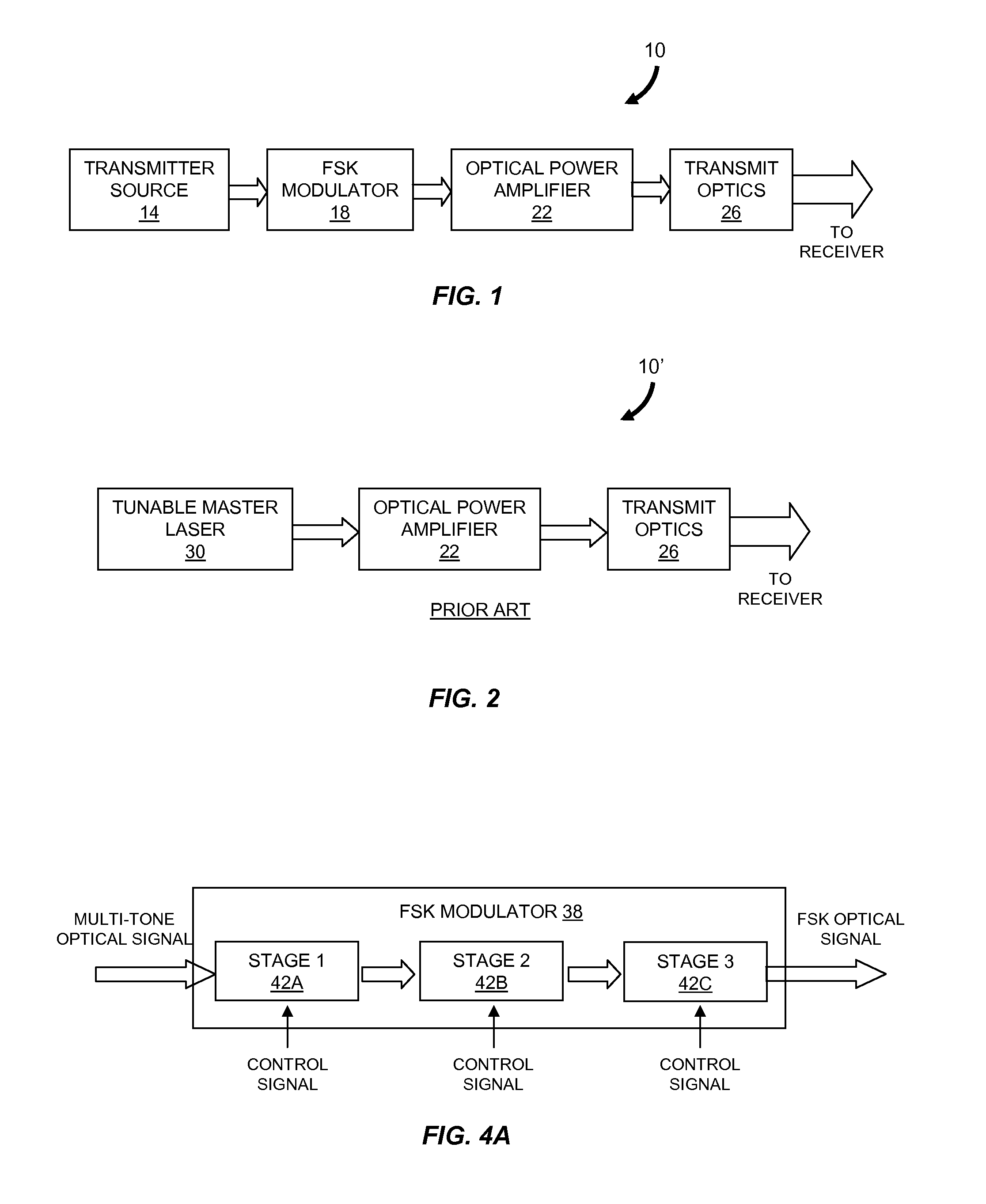
[0010]In another aspect, the invention features an FSK modulator for optical communications. The FSK modulator includes a first filter stage and a second filter stage. The first filter stage has an input optical path, an output optical path and a first microring resonator. The input optical path receives a multi-tone optical signal. The first microring resonator has a first optical path length and is disposed between the input and output optical paths. An electro-optic modulator is disposed on the first microring resonator to modulate the first optical path length in response to a first control signal. A first filtered optical signal having a subset of the tones in the multi-tone optical signal is provided in the output optical path of the first filter stage. The second filter stage has an input optical path in optical communication with the output optical path of the first filter stage, an output optical path and a second microring resonator. The second microring resonator has a second optical path length and is disposed between the input and output optical paths of the second filter stage. An electro-optic modulator is disposed on the second microring resonator to modulate the second optical path length in response to a second control signal. A second filtered optical signal having a subset of the tones in the first filtered optical signal is provide in the output optical path of the second filter stage.
[0011]In still another aspect, the invention features an FSK modulator for optical communications. The FSK modulator includes a first interferometer and a second interferometer. The first interferometer has a first arm and a second arm. At least one electro-optic modulator electrode is disposed on the first arm. The second interferometer is in optical communication with the first interferometer and has a first arm and a second arm. At least one electro-optic modulator electrode is disposed on the first arm of the second interferometer. The numbers of electro-optic modulator electrodes of the first and second interferometers are different and a length of at least one of the electro-optic modulator electrodes of one of the interferometers is less than the lengths of the electro-optic modulator electrodes of the other interferometer. At least one tone of a multi-tone optical signal received at one of the interferometers is selected for transmission through the first and second interferometers according to a plurality of binary voltage signals applied to the electro-optic modulator electrodes of the first and second interferometers.
[0012]In yet another aspect, the invention features an FSK modulator for optical communications. The FSK modulator includes a first filter stage and a second filter stage. The first filter stage has an input optical path, an output optical path and a first microring resonator. The input optical path receives a multi-tone optical signal. The first microring resonator has a first optical path length and is disposed between the input and output optical paths. At least one electro-optic modulator electrode is disposed on the first microring resonator to modulate the first optical path length in response to at least one binary control signal. A first filtered optical signal having a subset of the tones in the multi-tone optical signal is provided in the output optical path of the first filter stage. The second filter stage has an input optical path in optical communication with the output optical path of the first filter stage, an output optical path and a second microring resonator. The second microring resonator has a second optical path length and is disposed between the input and output optical paths of the second filter stage. At least one electro-optic modulator electrode is disposed on the second microring resonator to modulate the second optical path length in response to at least one binary control signal. The numbers of electro-optic modulator electrodes in the first and second microring resonators are different and a length of at least one of the electro-optic modulator electrodes of one of the microrings is less than the lengths of the electro-optic modulator electrodes of the other microring. At least one tone of the multi-tone optical signal is selected for transmission through the first and second filter stages according to the binary voltage signals applied to the electro-optic modulator electrodes of the first and second microrings.

Problems solved by technology

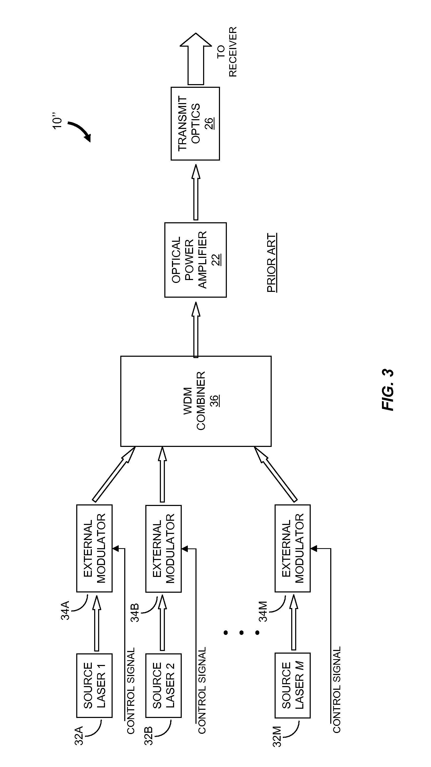
While the transmitter configuration 10″ illustrated in FIG. 3 is useful at high symbol rates (e.g., rates exceeding 40 GHz), the complexity of the transmitter is impractical for a large number M of source lasers 32.

Method used


Image

  • Modulator for frequency-shift keying of optical signals
  • Modulator for frequency-shift keying of optical signals
  • Modulator for frequency-shift keying of optical signals

Examples


Embodiment Construction

[0032]In brief overview, the invention relates to an FSK modulator and a method for large-alphabet (i.e., many different transmission frequencies) FSK modulation at high symbol rates (e.g., greater than 40 GHz). The method is based on filtering of a multi-tone optical source such as a mode-locked laser which provides a comb distribution of tones. A frequency-selective component selects for transmission a subset of the tones (e.g., “alternate” tones) in the comb distribution. A second frequency-selective component selects a subset of the tones from the comb distribution provided by the first frequency-selective component. Still more frequency-selective components can be used according to the number of tones supplied by the multi-tone optical source to the FSK modulator. The optical signal exiting the last frequency-selective component of the FSK modulator includes only a single tone which corresponds to the symbol to be transmitted. In one embodiment the frequency-selective component...


PUM


Abstract

Described are an FSK modulator and a method for large-alphabet FSK modulation. The FSK modulator and the method are based on filtering of a multi-tone optical source such as a mode-locked laser which provides a comb distribution of tones. A frequency-selective component selects for transmission a subset of the tones. In various embodiments the frequency-selective component is a Mach-Zehnder interferometer filter or a microring resonator filter. A second frequency-selective component selects a subset of the tones from the comb distribution provided by the first frequency-selective component. Still more frequency-selective components can be used according to the number of tones supplied by the multi-tone optical source to the FSK modulator. The optical signal exiting the last frequency-selective component includes only a single tone which corresponds to the symbol to be transmitted.

Description

RELATED APPLICATION[0001]This application claims the benefit of the earlier filing date of U.S. Provisional Patent Application Ser. No. 60 / 895,756, filed Mar. 20, 2007, titled “High-Speed Modulator for Frequency-Shift Keying,” the entirety of which is incorporated herein by reference.GOVERNMENT RIGHTS IN THE INVENTION[0002]This invention was made with United States government support under Contract No. FA8721-05-C-0002 awarded by the United States Air Force. The government may have certain rights in the invention.FIELD OF THE INVENTION[0003]The present invention relates generally to optical communications based on frequency-shift keying (FSK). More particularly, the invention relates to large-alphabet FSK modulation at high symbol rates using a serial configuration of filter stages based upon Mach-Zehnder interferometers or microring resonators.BACKGROUND OF THE INVENTION[0004]Power efficient optical links are useful for a number of applications such as high-bandwidth free-space com...

Claims


Application Information

Patent Timeline
Patent Type & Authority Applications(United States)
IPC IPC(8): H04B10/08H04B10/04
CPCH04B10/5051H04B10/5563H04B10/548
Inventor ROBINSON, BRYAN S.BOROSON, DON M.HAMILTON, SCOTT A.SAVAGE, SHELBY J.
Owner MASSACHUSETTS INST OF TECH
Learn More