
Compact wireless recessed sensor with plunger switch

a wireless sensor and plunger switch technology, applied in the direction of magnetic/electric field switches, mechanical actuation of burglar alarms, instruments, etc., can solve the problems of not being compact enough to be installed after-market into windows and doors without voiding the window or door manufacturer's warranty

Active Publication Date: 2010-04-29
ROYNE INDS NASCOM
View PDF8 Cites 24 Cited by
  • Summary
  • Abstract
  • Description
  • Claims
  • Application Information

AI Technical Summary

Benefits of technology

[0009]According to another aspect of the invention, the sensor housing may be assembled in a longitudinally-oriented position to achieve longitudinal compactness of size. According to this embodiment, the plunger switch is positioned directly atop of the sensor electronics and power source to provide a compact overall height.
[0010]According to yet another aspect of the invention, a moisture barrier, such as a plastic wall, may be used to isolate the plunger switch and magnet elements from the electronic portions of the wireless sensor (namely, a printed circuit board“PCB” connected to the microprocessor), which protects otherwise sensitive electronic elements from potential casual water ingress from weather or cleaning
[0012]As discussed in the Background of the Invention, other wired recessed plunger switches can be seen to be at least 1.3″ long (or greater) and typically 0.75″ in diameter. Other wireless recessed switches (without a plunger switch) can be seen to be at least 2.5″ long and 0.75″ in diameter. This invention combines both the plunger switch, such as a roller-type plunger, and a wireless sensor within the approximate dimensions in the ranger of an inch or less, and in a preferred form approximately less than 1.1 inch long and 0.75 inch in diameter. The compact size makes the present invention ideally suitable for a variety of wireless security systems.

Problems solved by technology

Such an example is found in Huckins et al., U.S. Pat. No. 5,155,460 B1, issued in reexamination on May 16, 2005 and entitled “Switch Housing with Magnetic Roller Plunger.” However, the Huckins invention is still hard wired and not sufficiently compact to be installed after-market into windows and doors without voiding the window or door manufacturer's warranty.

Method used


Image

  • Compact wireless recessed sensor with plunger switch
  • Compact wireless recessed sensor with plunger switch
  • Compact wireless recessed sensor with plunger switch

Examples


Embodiment Construction

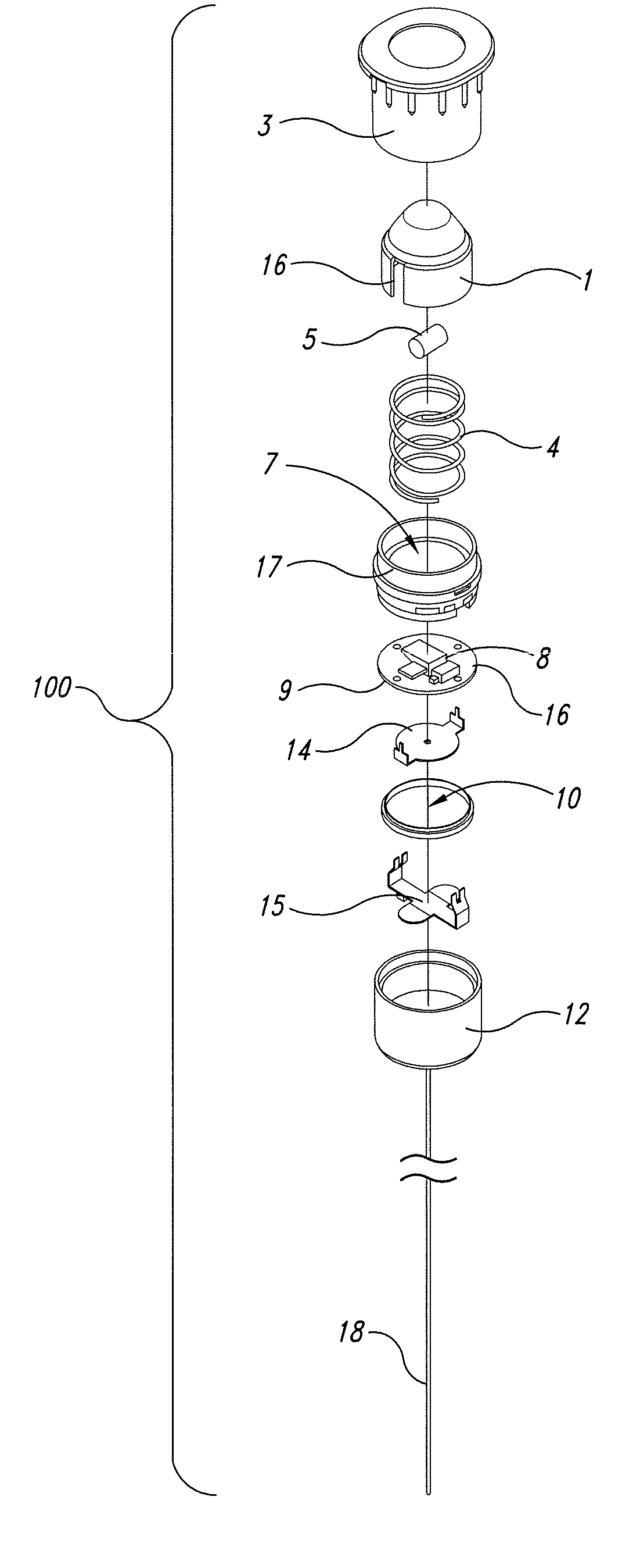
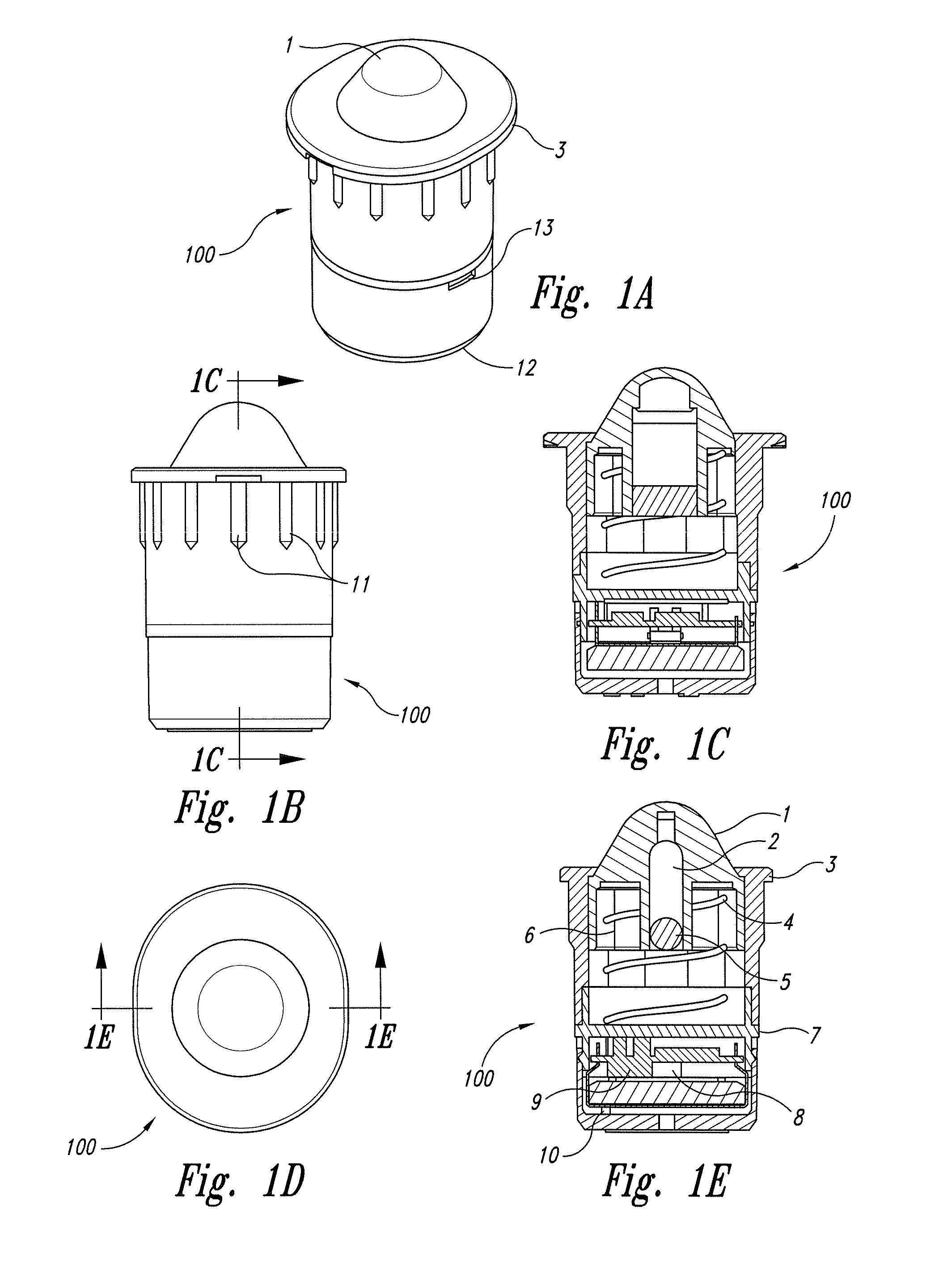
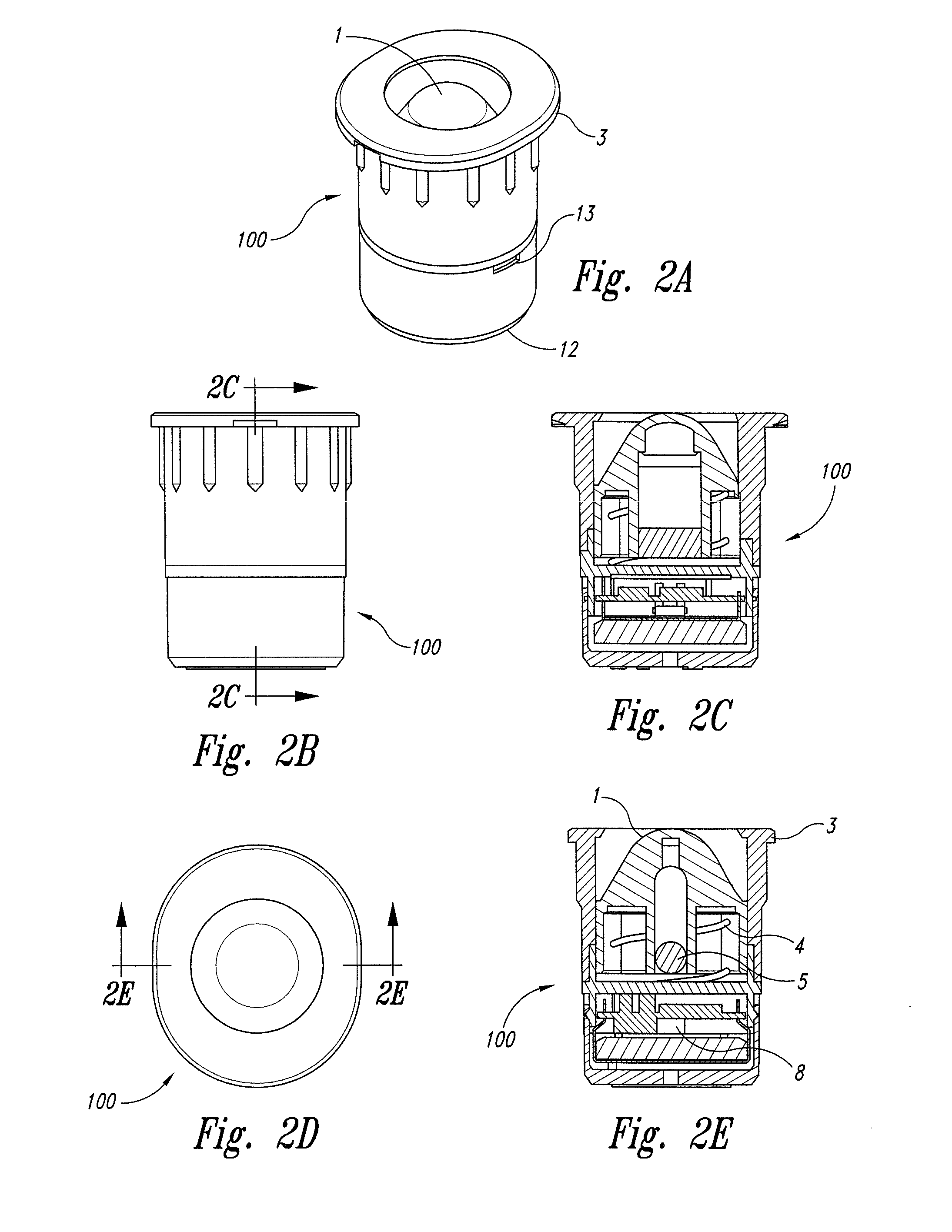
[0034]Referring to FIGS. 1-3 (including all subparts), an embodiment of the present invention illustrates a compact wireless recessed sensor have a plunger switch (100). According to one embodiment of the invention, a hollow, dome-shaped plunger (1) has a small rod type magnet (5) that is inserted within the plunger in a small hollow in its center (2) and fastened in place. The plunger is supported within a frame assembly composed of a spring housing (3) and a middle frame (7) with a spring (4), that allows the plunger to move between a fully open position (FIGS. 1(a)-(e)) and a fully closed position (FIGS. 2(a)-(e)).

[0035]The frame which includes the spring housing (3) and the middle frame (7), are fastened together during assembly (e.g., glued or sonic welded) to keep the plunger (1), magnet (5), and spring (4) from being removed from the frame. The spring may be inserted inside the outer wall of the hollow plunger (6). The plunger (1), spring housing (3), and middle housing (7) m...


PUM


Abstract

A compact wireless security sensor having a magnetically operated plunger switch. The compact nature of the sensor of the present invention makes it ideal for being substantially concealing into a door frame or window as part of a wireless security system. The sensor unit includes a housing having an inner end, an outer end, and a magnet positioned within a moveable plunger, and an antenna, preferably a flexible wire antenna. The housing further contains a sensor switch, a microprocessor with a PCB, a wireless transmitter, such as an RF transmitter, and a power source, such as a small coin cell battery, for emitting signals to a master station or controller when the plunger switch is depressed and activates the internal sensor switch.

Description

RELATED APPLICATION[0001]The present application claims priority to U.S. Provisional Patent Application Serial No. 61 / 109,079, filed on Oct. 28, 2008, and entitled “Compact Wireless Recessed Sensor with Plunger Switch.”TECHNICAL FIELD[0002]The present invention relates to compact wireless sensors with plunger switches, and, particularly for the insertion of these type sensors within door frames as a means for detecting intrusion.BACKGROUND OF THE INVENTION[0003]Magnetic plunger switches are well known in the industry, even for use as a sensor for sensing the presence of a movable object such as a door or window. Such an example is found in Huckins et al., U.S. Pat. No. 5,155,460 B1, issued in reexamination on May 16, 2005 and entitled “Switch Housing with Magnetic Roller Plunger.” However, the Huckins invention is still hard wired and not sufficiently compact to be installed after-market into windows and doors without voiding the window or door manufacturer's warranty.[0004]Other ma...

Claims


Application Information

Patent Timeline
Patent Type & Authority Applications(United States)
IPC IPC(8): H01H36/00
CPCH01H36/004G08B13/08
Inventor SCHEBEL, DEAN DAVIDCARLSON, JULIAN P.VANDEVANTER, RUSSELL E.
Owner ROYNE INDS NASCOM
Learn More