
Knee airbag device

a knee airbag and knee technology, applied in the direction of pedestrian/occupant safety arrangement, vehicular safety arrangement, vehicle components, etc., can solve the problems of increased man-hour required to assemble the knee airbag device and increased cos

Inactive Publication Date: 2010-04-29
TOYOTA JIDOSHA KK
View PDF7 Cites 3 Cited by
  • Summary
  • Abstract
  • Description
  • Claims
  • Application Information

AI Technical Summary

Benefits of technology

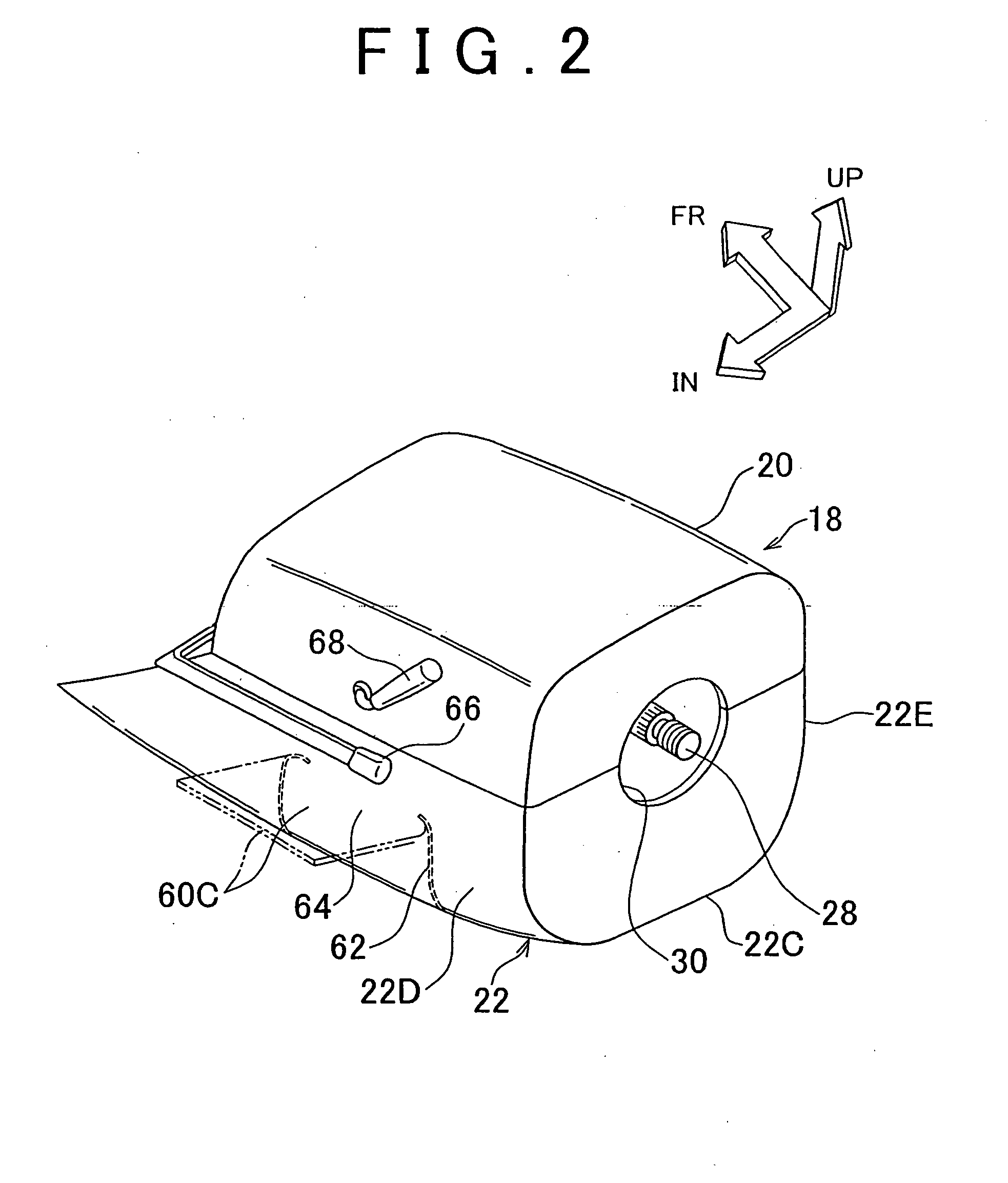
[0007]The invention provides a knee airbag device in which a knee airbag is prevented from directly contacting an interfering object such as a key accessory or a tilt lever when the knee airbag is inflated and deployed, without the need of increasing the number of components.
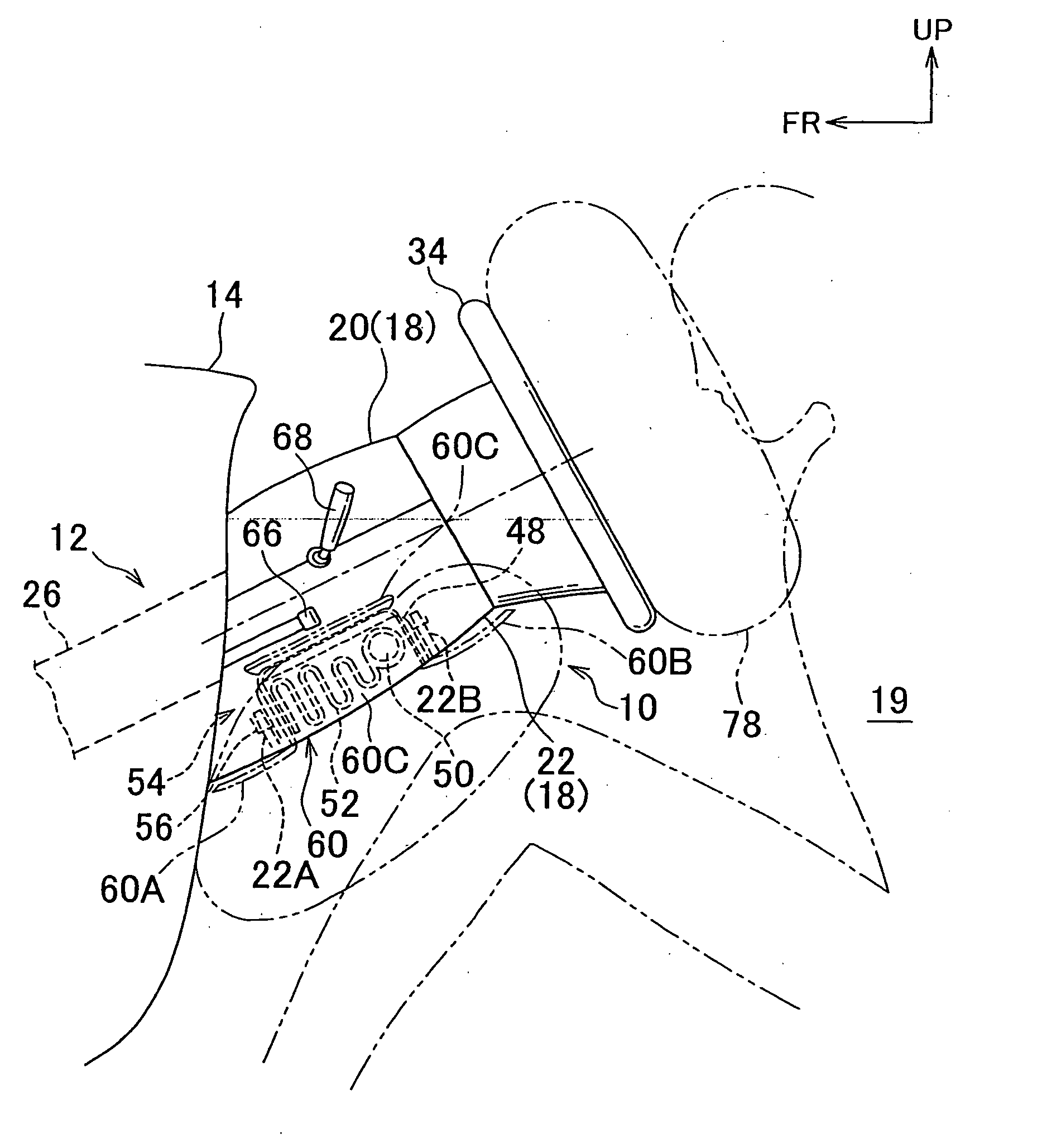
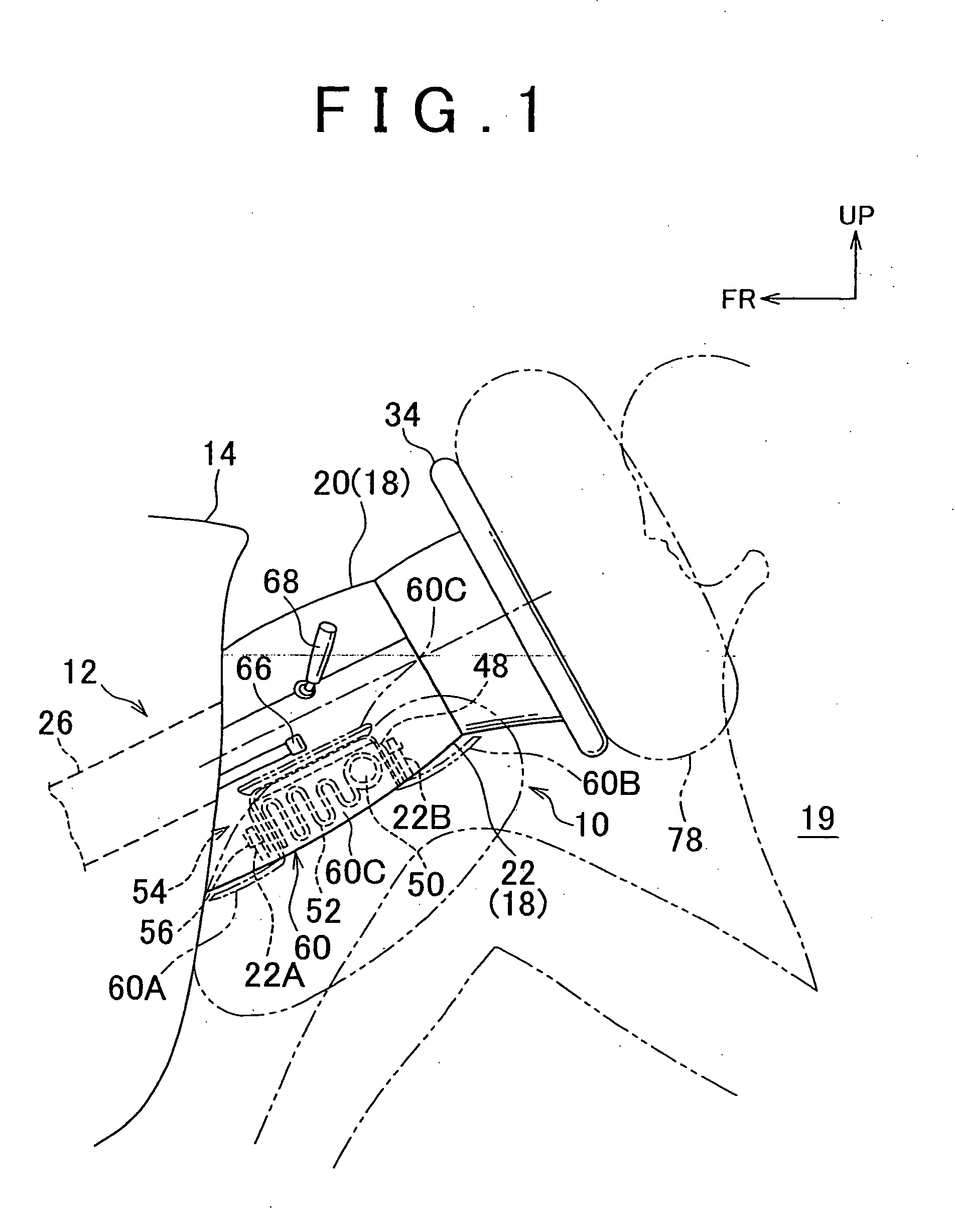
[0009]According to the first aspect, when a collision occurs or when it is predicted that the collision will occur, the gas generation device generates gas, and the knee airbag, which is stored in the folded state inside the column cover, is inflated by the gas. The airbag door is provided in the lower portion of the column cover. When the inflation pressure of the knee airbag is equal to or higher than the predetermined value, the airbag door is opened. As a result, the knee airbag is inflated and deployed, and thus, the knee airbag restrains knees of an occupant.
[0010]According to the above-described aspect, at least the portion of the airbag door is positioned between the interfering object that is positioned in the area on the side of the column cover, and at least the portion of the knee airbag that is inflated and deployed. That is, before the knee airbag is inflated and deployed, at least the portion of the airbag door is opened, and positioned between the interfering object and at least the portion of the knee airbag. This prevents at least the portion of the knee airbag from directly interfering with the interfering object.
[0012]As described above, in the knee airbag device according to the above-described aspect, it is possible to obtain the advantageous effect that when the knee airbag is inflated and deployed, the knee airbag is prevented from directly contacting the interfering objects such as the key accessory and the tilt lever, without the need of increasing the number of components.
[0016]In the knee airbag device according to the above-described aspect, it is possible to obtain the advantageous effect that when the knee airbag is inflated and deployed, the knee airbag is reliably prevented from directly contacting the interfering objects such as the key accessory and the tilt lever.
[0020]In the knee airbag device according to the above-described aspect, it is possible to obtain the advantageous effect that when the knee airbag is inflated and deployed, the knee airbag is reliably prevented from directly contacting the interfering objects such as the key accessory and the tilt lever.

Problems solved by technology

In this case, however, the number of components, and the number of man-hour required to assemble the knee airbag device are increased, and accordingly, the cost is increased.

Method used


Image

  • Knee airbag device
  • Knee airbag device
  • Knee airbag device

Examples


modified example

[0051]Next, modified examples will be described.

first modified example

[0052]In a first modified example shown in FIG. 4A to FIG. 4C, an airbag door 80 is divided in a manner different from the manner in which the airbag door 60 in the above-described embodiment is divided. The airbag door 80 includes two doors (right and left doors), that is, a right door 80B and a left door 80A. The right door 80B extends in the bottom wall portion and the right side wall portion of the column lower cover 22. The left door 80A extends in the bottom wall portion and the left side wall portion of the column lower cover 22. The right door 80B and the left door 80A are widely opened rightward and leftward, respectively. In this case as well, it is possible to obtain the same advantageous effects as those obtained in the above-described embodiment.

second modified example

[0053]In a second modified example shown in FIG. 5A to FIG. 5C, an airbag door 90 is divided in a manner different from the manner in which the airbag door 60 in the above-described embodiment is divided. A bottom front door 90A and a bottom rear door 90B are formed in the bottom wall portion of the column lower cover 22. A right front door 90C and a right rear door 90D are formed in the right side wall portion of the column lower cover 22, and a left front door 90E and a left rear door (not shown) are formed in the left side wall portion of the column lower cover 22. Accordingly, the airbag door 90 is divided into six portions. When the knee airbag 52 is deployed, the right rear door 90D pivots around a hinge portion 92, and covers the key accessory 72. The axis of the hinge portion 92 extends substantially in the direction of the height of the steering column 12 (i.e., a substantially vertical direction).


PUM


Abstract

A knee airbag device includes an airbag module and an airbag door. The airbag module, which is provided inside a column cover that covers the rear end portion of a steering column, includes gas generation device that generates gas when a collision occurs, and a knee airbag that is inflated and deployed from a folded state when the knee airbag receives the gas from the gas generation device. The airbag door, which is provided in the lower portion of the column cover, is opened when the inflation pressure of the knee airbag is equal to or higher than a predetermined value. When the knee airbag is deployed, at least a portion of the airbag door is positioned between an interfering object that is positioned in an area on the side of the column cover, and at leaser a portion of the knee airbag.

Description

BACKGROUND OF THE INVENTION[0001]1. Field of the Invention[0002]The invention relates to a knee airbag device that includes a knee airbag that is inflated and deployed to restrain knees of an occupant when a collision occurs.[0003]2. Description of the Related Art[0004]Various knee airbag devices have been proposed to protect the knees of an occupant. For example, each of Japanese Patent No. 2759065 and Japanese Patent Application Publication No. 9-104317 (JP-A-9-104317) describes a knee airbag device in which an airbag module is disposed inside a column lower cover that covers the rear end portion of a steering column.[0005]However, in the above-described technology, when the knee airbag is inflated and deployed, the knee airbag may contact a key accessory (a key chain or the like) and a manual tilt lever provided on the side of the column cover. Accordingly, the above-described knee airbag device needs to be improved in this regard.[0006]Reinforcement cloth or the like may be prov...

Claims


Application Information

Patent Timeline
Patent Type & Authority Applications(United States)
IPC IPC(8): B60R21/215B60R21/203B60R21/20B60R21/206
CPCB60R21/203B60R2021/161B60R21/215B60R21/206
Inventor FUKAWATASE, OSAMUIMAMURA, KENJISANADA, AKIYOSHIBITO, KAZUAKIADACHI, YUICHI
Owner TOYOTA JIDOSHA KK
Learn More