
Solar panels systems and methods

a solar panel and solar panel technology, applied in the direction of photovoltaic supports, sustainable buildings, roofing, etc., can solve the problems of roof penetration and wind load, difficult installation and fragile once installed of pv cell systems, and increasing the use of pv cells as an alternative to other sources of energy

Inactive Publication Date: 2010-04-29
OPEN ENERGY CORP
View PDF60 Cites 11 Cited by
  • Summary
  • Abstract
  • Description
  • Claims
  • Application Information

AI Technical Summary

Benefits of technology

[0008]In some embodiments, solar cells may be in a sealed assembly. The sealed assembly may provide the solar cell with some protection from weather, sunlight, dust, etc. This might increase the time that the solar cell functions, thereby increasing the life of the solar panel. A solar panel that lasts longer is less expensive to operate over the course of its life.
[0010]Some embodiments include wind clips that are configured to help secure the solar panel to, for example, a roof. The wind clips may provide additional securing force to help ensure that the solar panel remains installed by clipping under an adjacent solar panel or roofing shingle. Tying multiple solar panels together by installing various panels over the top of wind clips on various other panels may help prevent, e.g., wind damage to the panels. The wind clip may help secure the solar panel against gusts of wind.

Problems solved by technology

The use of PV cells as an alternative to other sources of energy has generally increased as power costs have increased.
Systems for mounting PV cells generally, however, are difficult to install and fragile once they are installed.
Installation often requires roof racks that may result in roof penetrations and wind loads.
Additionally, to generate a significant amount of power, the system generally must include a large number of panels with PV cells, which can create wiring issues with respect to connections to the existing utility systems.
Systems for mounting PV cells also tend to lack curb appeal and may change the aesthetics of a structure, e.g., a residential structure.

Method used


Image

  • Solar panels systems and methods
  • Solar panels systems and methods
  • Solar panels systems and methods

Examples


Embodiment Construction

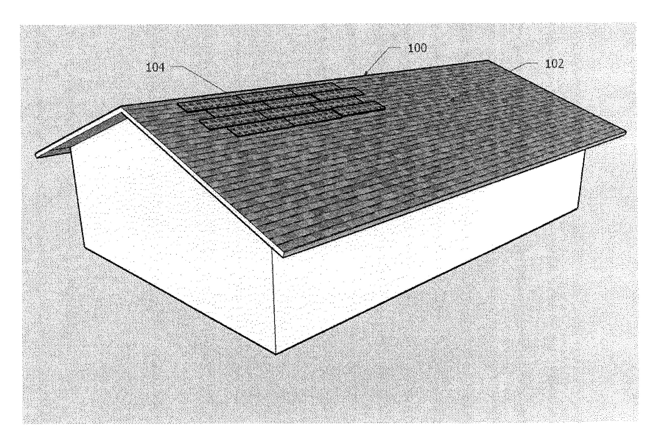
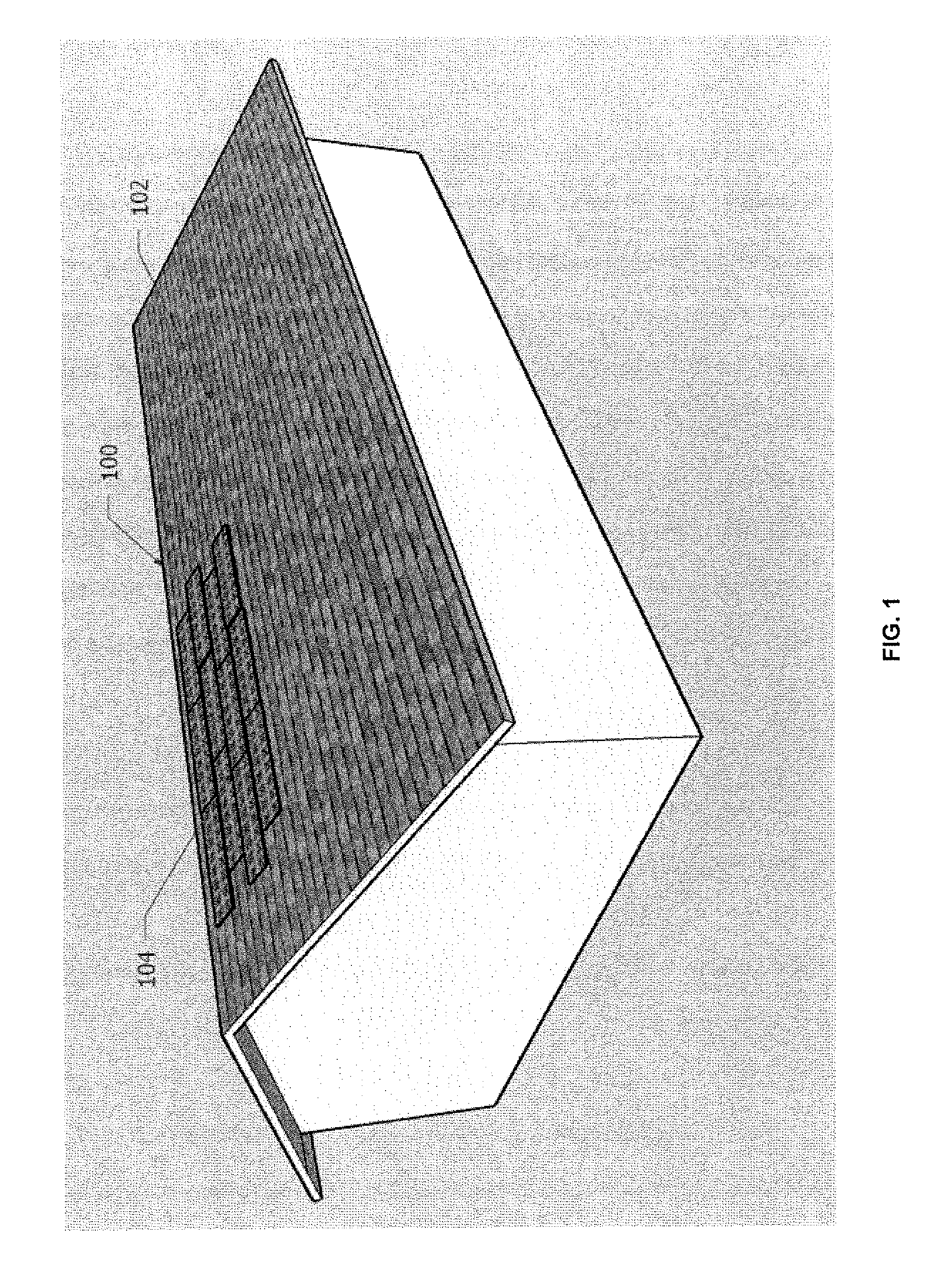
[0005]According to various embodiments of the invention, systems and methods for attaching a solar panel to a roof are provided. A solar panel generally comprises a solar laminate and a frame supporting the solar laminate. The frame may be configured to interface with a conventional shingle in an overlapping fashion. In some embodiments, the frame includes an integrated rain-rail configured to provide a conduit for rainwater and may or may not mate with a rain-rail or other detail on another solar panel providing a mechanical interconnection between the panels. The solar cell may also include a tack-down strip configured to connect the solar panel to a roof. This tack-down strip may be configured to overlap a shingle on a roof.

[0006]In some embodiments, the solar panel might include a jumper configured to reverse polarity. The jumper can be used to string a plurality of solar panels together. The solar panels may be connected in series, in parallel, or a combination thereof. This ca...


PUM


Abstract

According to various embodiments of the invention, systems and methods for attaching a solar panel to a roof are provided. A solar panel generally comprises a solar cell and a frame enclosing the solar cell. The frame may be configured to interface with a conventional roof shingle in an overlapping fashion. In some embodiments, the frame includes an integrated rain-rail configured to provide a conduit for rainwater and mate with a rain-rail on another solar panel providing a mechanical interconnection between the panels. The solar cell may also include a tack-down strip configured to connect the solar panel to a roof. This tack-down strip may be configured to overlap a shingle on a roof.

Description

TECHNICAL FIELD[0001]The present invention relates to systems and methods for solar power generation, and more particularly, to systems and methods for solar panels capable of rooftop installation.DESCRIPTION OF THE RELATED ART[0002]Increasing oil prices and environmental concerns have recently highlighted the desire to decrease the dependence on fossil fuels. This desire has stimulated research into clean and renewable ways to produce electricity for the global marketplace. Solar power is a viable option because it is a clean form of energy with a virtually unlimited supply. Technological innovations and improvements are generally reducing the costs associated with installing, operating, and maintaining solar power equipment. Furthermore, conversion efficiencies have dramatically increased over the years, thereby reducing the size of the equipment necessary to harvest energy produced by the sun.[0003]In some cases, solar energy systems may be used to avoid the use of oil or other f...

Claims


Application Information

Patent Timeline
Patent Type & Authority Applications(United States)
IPC IPC(8): E04D13/18
CPCY02B10/12H02S20/25H02S20/23Y02E10/50Y02B10/10
Inventor FRANK, CHRISTOPHERTUTON, GARYSCOTT, BRYAN
Owner OPEN ENERGY CORP
Learn More