Asymmetric one-legged wire guide for fishing rod

a technology fishing rod, which is applied in the field of asymmetric one-legged wire guide for fishing rod, can solve the problems of adversely affecting the flying of fishing line and the feel of use, and achieve the effects of reducing the slipping resistance of fishing line, facilitating mounting to the fishing rod, and enhancing the above-mentioned

Inactive Publication Date: 2010-04-29
TAKEMOTO MASAKI
View PDF44 Cites 0 Cited by
  • Summary
  • Abstract
  • Description
  • Claims
  • Application Information

AI Technical Summary

Benefits of technology

[0011]The asymmetric one-legged wire guide for a fishing rod of the present invention, constructed as described above, provides the following effects.
[0019]It is an object of the present invention to provide an asymmetric one-legged wire guide which prevents entanglement of the line guide and the fishing line and which helps to reduce the slipping resistance of the fishing line at the line guide portion.

Problems solved by technology

Therefore, the slipping resistance offered to the fishing line, in particular, the resistance at the time of slipping start is large, which adversely affects the flying of the fishing line at the time of surf casting and the feel of use.

Method used


Image

  • Asymmetric one-legged wire guide for fishing rod
  • Asymmetric one-legged wire guide for fishing rod
  • Asymmetric one-legged wire guide for fishing rod

Examples


first embodiment

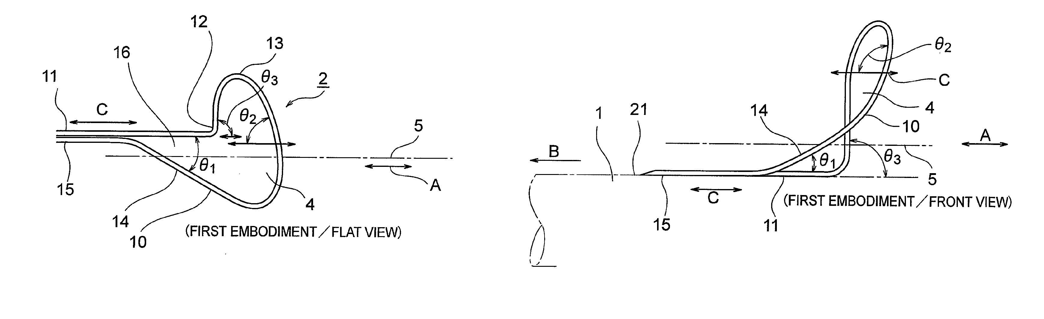
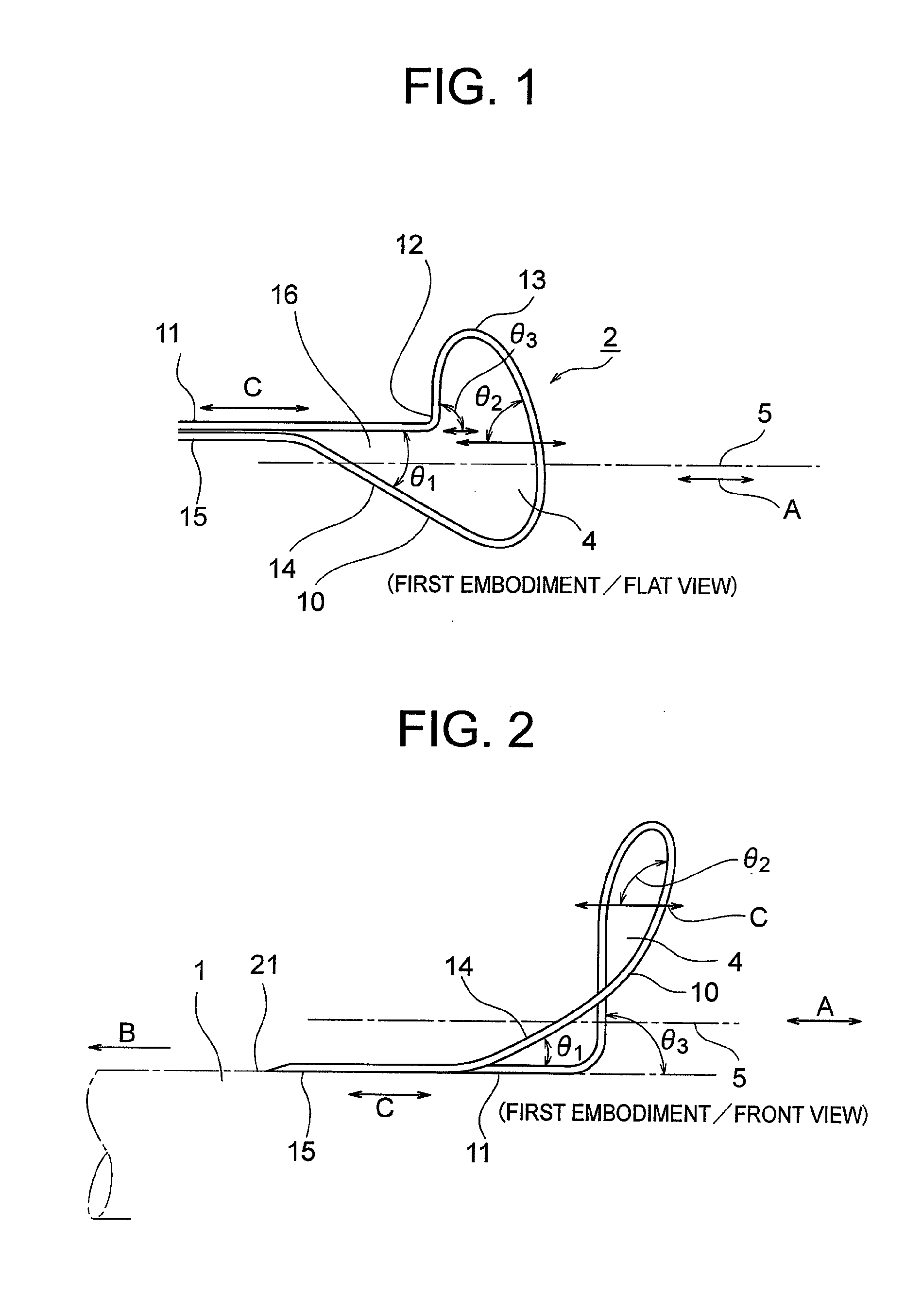
[0042]FIGS. 1 and 2 illustrate the present invention. The wire guide 2 is fixed to the surface 21 of the fishing rod 1 by a mounting thread (not shown) or the like. The wire guide 2 is as illustrated in FIG. 1 in flat view, and is as illustrated in FIG. 2 in front view.

[0043]The wire guide 2 is formed by bending a single wire 10. One end portion of the wire 10 is formed as a linear first leg 11 which extends toward the other second leg 15 to form a loop-like line guide portion 4 in which a bent portion 12, an arcuate portion 13, and a linear portion 14 are integrally connected with each other.

[0044]In the flat view of FIG. 1, the first and second legs 11 and 15 are bundled together and arranged side by side on the fishing rod 1. The bent portion 12, the arcuate portion 13, and the linear portion 14 integrally rise from the legs 11 and 15 at different angles with respect to the longitudinal direction C of the legs 11 and 15. The difference between the rising angles ranges from 30 deg...

second embodiment

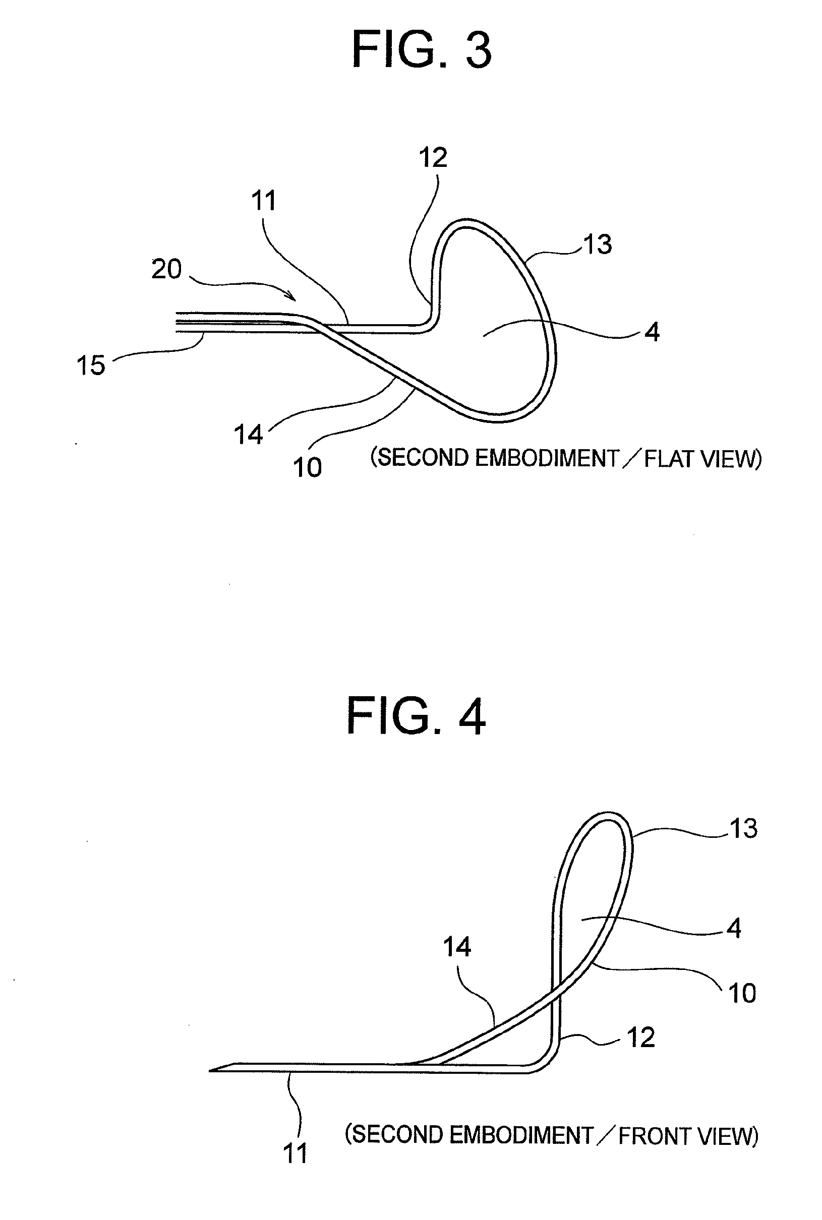
[0046]FIGS. 3 and 4 illustrate the present invention, in which the second leg 15 is raised over the first leg 11 and is caused to cross the same, with the linear portion 14 and the first leg 11 forming a crossing portion 20.

[0047]The legs 11 and 15 extend on the fishing rod 1 toward the rod base B, with the legs 11 and 15 supporting the line guide portion 4 as a single leg.

[0048]The other portions are the same as those of FIGS. 1 and 2, and hence the same portions are indicated by the same reference numerals, and description thereof is omitted.

[0049]FIGS. 5 and 6 illustrate a third embodiment of the present invention, in which the configuration of the arcuate portion 13 is horizontally reversed to that of the first embodiment. The portions that are the same as or equivalent to those of FIGS. 1 and 2 are indicated by the same reference numerals and description thereof is omitted.

[0050]FIGS. 7 and 8 illustrate a fourth embodiment of the present invention, in which the configuration of...


PUM


Abstract

The conventional wire guide, constructed as described above, has the following problems.In the case of the above-mentioned construction of the line guide portion as illustrated in FIGS. 17 and 18, the angle formed by the portion where the line guide portion (4) and the fishing line are most strongly held in contact with each other, that is, the portion of the line guide (4) at maximum distance from the surface (21) of the fishing rod (1), and by the longitudinal direction of the base (3), that is, the advancing direction A of the fishing line (5), is a right angle (θ4). Therefore, the slipping resistance offered to the fishing line, in particular, the resistance at the time of slipping start is large, which adversely affects the flying of the fishing line at the time of surf casting and the feel of use.In order to solve this problem, an asymmetric one-legged wire guide for a fishing rod, comprising:a loop-like line guide portion (4) formed by bending a single wire (10) and;a pair of first linear leg (11) and second linear leg (15) formed respectively at both ends of the wire (10) and bundled together so as to be fore and aft with respect to each other in an advancing direction (A) of a fishing line (5) passing the line guide portion (4),wherein an angle (θ2) formed by a portion of the line guide portion (4) in contact with the fishing line (5) which is at maximum distance from a surface (21) of a fishing rod (1) and by a longitudinal direction (C) is an angle other than a right angle with respect to the longitudinal direction (C).

Description

BACKGROUND OF THE INVENTION[0001]1. Field of the Invention[0002]The present invention relates to an asymmetric one-legged wire guide for a fishing rod, in particular, to a novel improvement for preventing entanglement of a line guide portion and a fishing line and for reducing slipping resistance of the fishing line at the line guide portion.[0003]2. Description of the Related Art[0004]No patent application has been filed on a wire guide for a fishing rod of this type conventionally in use and on the market, and hence there is no disclosure in this regard in patent documents or the like. FIGS. 17, 18, and 19 illustrate a typical construction of a wire guide of this type.[0005]In FIGS. 17, 18, and 19, a fishing rod is indicated by a reference numeral 1; a base 3 (corresponding to a leg) of a wire guide 2 is fixed to the surface of the fishing rod 1 through an intermediation of a fishing line (not shown), and a round-ring-shaped line guide portion 4 is integrally provided on the base ...

Claims


Application Information

Patent Timeline
Patent Type & Authority Applications(United States)
IPC IPC(8): A01K87/04
CPCA01K87/04
Inventor TAKEMOTO, MASAKI
Owner TAKEMOTO MASAKI
Why Eureka
Try Eureka